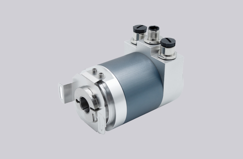
The CR58-1024R19A01 is supplied with a controlled production lead time of approximately 10 working days, ensuring continuity for scheduled maintenance and automation upgrade projects. This model is engineered as a 1:1 technical replacement for parallel absolute encoder systems that require strict mechanical and electrical equivalence. Mounting geometry, shaft tolerances, signal mapping, and connector configuration are reproduced according to verified specifications, allowing direct installation without structural rework or PLC logic modification. When application conditions demand alternative interface layouts or mechanical adjustments, functionally equivalent customized variants can be delivered while preserving original system performance.
From a technical depth perspective, this encoder utilizes a parallel absolute data architecture that outputs simultaneous multi-bit position information, eliminating sequential communication delay and ensuring deterministic feedback timing in high-speed motion environments. The internal optical scanning assembly is optimized for signal contrast stability, minimizing phase deviation and reducing cumulative positioning error during continuous operation. Advanced circuit shielding and signal conditioning enhance immunity to electromagnetic interference, which is critical in electrically noisy industrial settings. The reinforced housing structure improves mechanical rigidity and thermal stability, maintaining measurement consistency under vibration and fluctuating ambient temperatures.
This solution is commonly implemented in CNC machining centers, automated packaging lines, robotic handling modules, and precision conveyor platforms where synchronized motion control and accurate position tracking directly influence throughput efficiency, repeatability, and long-term equipment reliability.
Technical data
| Parameter | Value |
|---|---|
| Resolution | 2 to 4096 positions / 360° |
| Measuring range | 2 to 4096 turns |
| Total number of positions | |
| Measurement position deviation | |
| Output frequency* | 30 kHz max. up to 10 Bit / 360°; 10 kHz max. from 11 Bit |
| Disc coding | Gray code |
| Output code, parallel | Gray or Natural Binary |
| Code sense, serial | CW or CCW (Signal input E2) |
| Logic polarity | Positive |
| Memory circuit | Store or not store, signal input E1 |
| Enable circuit (for bus operation) | Active or inactive, (signal input E1) |
| Sensor system | GaAlAs diodes, photo-transistor array |
| Parallel output circuits | A = Open collector Darlington; B = Open collector, TTL compatible; C = Open emitter Darlington; D = Push-pull, Totem-pole |
| Serial output SSI | Differential data output to RS 422 |
| Clock input SSI | Differential (opto-coupler) for data driver to RS 422 |
| Supply voltage range | +11 V to +26 VDC |
| Supply current | Parallel: 90 mA typ. / 120 mA max.; Serial GSI: 130mA typ. / 160mA max. |
| Operating speed | 3000 rpm max. (continuous); 4000 rpm max. (short period) |
| Angular acceleration | 10° rad/s² max. |
| Inertial mass of rotor | ≤ 5 Ncm (8 Ncm - CR 66) |
| Wind-up torque | ≤ 1 Nm (4 Ncm - CR 66) |
| Permissible axial and radial shaft load | 250 N max. |
| Bearing life expectancy | 10⁹ revolutions |
| Operating temperature range | -20°C to +60°C |
| Storage temperature range | -25°C to +70°C |
| Permissible rel. humidity | 85% without condensation |
| Resistance to shock | 200 m/s², 11 ms (DIN IEC 68) |
| Resistance to vibration | 5 Hz..1000 Hz; 100 m/s² (DIN IEC 68) |