The CR58-4096G21C01 is available with a standard production lead time of approximately 10 working days under stable manufacturing conditions. It is engineered as a high-compatibility custom replacement for parallel absolute encoder installations that require strict mechanical and electrical interchangeability. The mounting flange geometry, shaft interface, signal bit allocation, and electrical pin configuration are aligned with existing system requirements to enable direct replacement. For time-sensitive maintenance projects, technically equivalent configurations can be arranged to maintain dimensional consistency and output logic integrity, helping reduce unexpected downtime during retrofit operations.
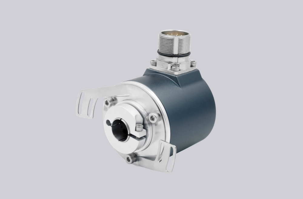
From an engineering standpoint, this encoder operates on a native parallel absolute output structure, transmitting simultaneous multi-bit position data without sequential communication latency. This architecture ensures deterministic response timing in closed-loop control systems where synchronization accuracy is critical. The internal optical measurement module is optimized for signal contrast precision and long-term stability, reducing drift across extended duty cycles. A reinforced metal enclosure improves structural rigidity and resistance to vibration, oil mist, and airborne contaminants common in industrial facilities.
This model is frequently deployed in rolling mills, automated assembly systems, synchronized conveyor platforms, and heavy-load motion control equipment where accurate real-time absolute positioning directly impacts operational safety, throughput efficiency, and system reliability.
Technical data
| Parameter | Value |
|---|---|
| Resolution | 2 to 4096 positions / 360° |
| Measuring range | 2 to 4096 turns |
| Total number of positions | |
| Measurement position deviation | |
| Output frequency* | 30 kHz max. up to 10 Bit / 360°; 10 kHz max. from 11 Bit |
| Disc coding | Gray code |
| Output code, parallel | Gray or Natural Binary |
| Code sense, serial | CW or CCW (Signal input E2) |
| Logic polarity | Positive |
| Memory circuit | Store or not store, signal input E1 |
| Enable circuit (for bus operation) | Active or inactive, (signal input E1) |
| Sensor system | GaAlAs diodes, photo-transistor array |
| Parallel output circuits | A = Open collector Darlington; B = Open collector, TTL compatible; C = Open emitter Darlington; D = Push-pull, Totem-pole |
| Serial output SSI | Differential data output to RS 422 |
| Clock input SSI | Differential (opto-coupler) for data driver to RS 422 |
| Supply voltage range | +11 V to +26 VDC |
| Supply current | Parallel: 90 mA typ. / 120 mA max.; Serial GSI: 130mA typ. / 160mA max. |
| Operating speed | 3000 rpm max. (continuous); 4000 rpm max. (short period) |
| Angular acceleration | 10° rad/s² max. |
| Inertial mass of rotor | ≤ 5 Ncm (8 Ncm - CR 66) |
| Wind-up torque | ≤ 1 Nm (4 Ncm - CR 66) |
| Permissible axial and radial shaft load | 250 N max. |
| Bearing life expectancy | 10⁹ revolutions |
| Operating temperature range | -20°C to +60°C |
| Storage temperature range | -25°C to +70°C |
| Permissible rel. humidity | 85% without condensation |
| Resistance to shock | 200 m/s², 11 ms (DIN IEC 68) |
| Resistance to vibration | 5 Hz..1000 Hz; 100 m/s² (DIN IEC 68) |