A tailored compatible encoder solution can be developed for the 8.9080.3131.3001 in maintenance, retrofit, replacement, and upgrade projects. This model belongs to a multiturn absolute encoder configuration with PROFIBUS DP communication, making it suitable for applications where fieldbus integration, continuous position tracking, and installation continuity must be preserved. Typical production lead time: 30 working days. The engineering objective is to match the original mounting logic, through-hollow-shaft structure, bus communication characteristics, and field wiring arrangement so that system modification work can be kept to a practical minimum.
Technical Overview of the 8.9080.3131.3001 Encoder
The 8.9080.3131.3001 is a multiturn absolute encoder with a PROFIBUS DP interface and RS485 physical layer. Its resolution architecture is scalable, with singleturn resolution from 1 to 8192 steps and multiturn capability from 1 to 4096 revolutions, reaching a maximum overall resolution of 25 bits. The code format is binary, and the encoder profile is class 2, which is relevant when maintaining compatibility with existing PLC or drive-side PROFIBUS parameter handling.
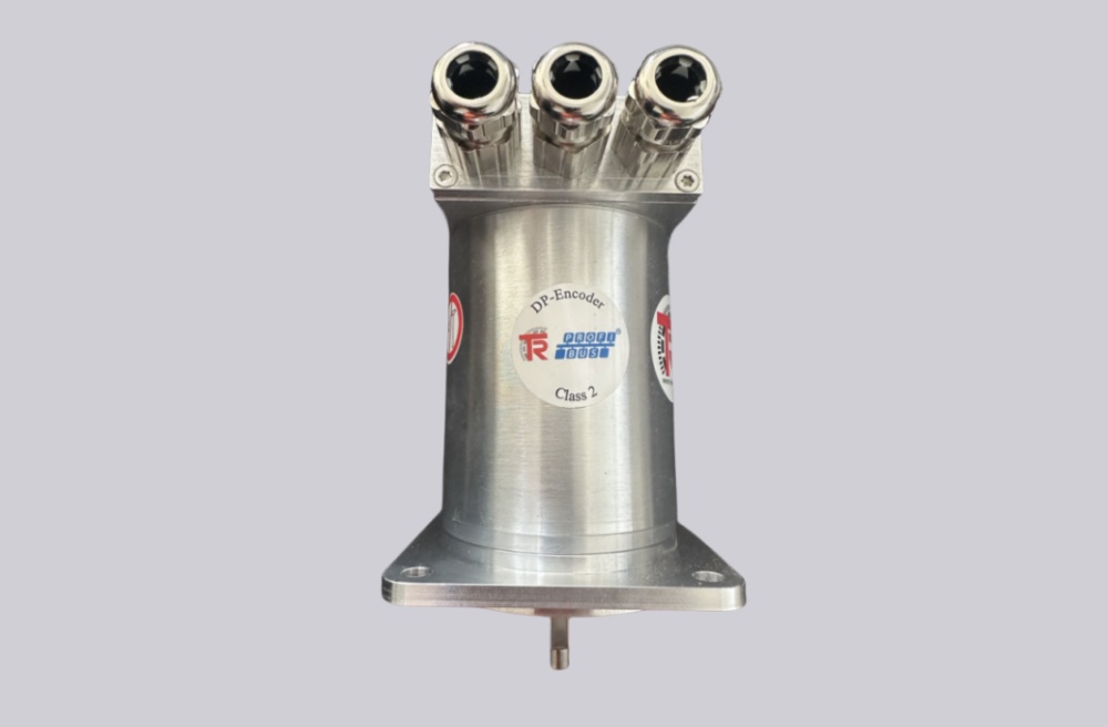
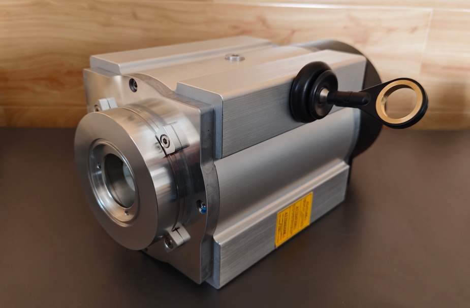
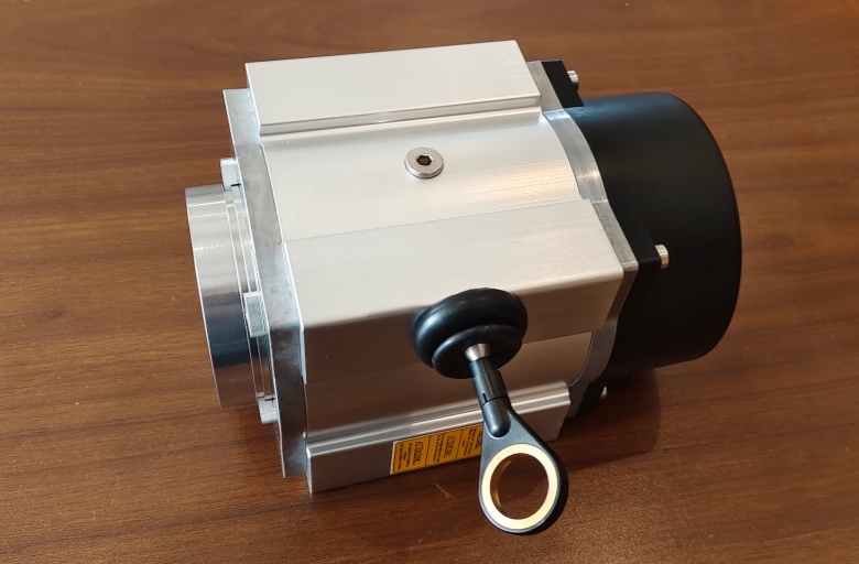
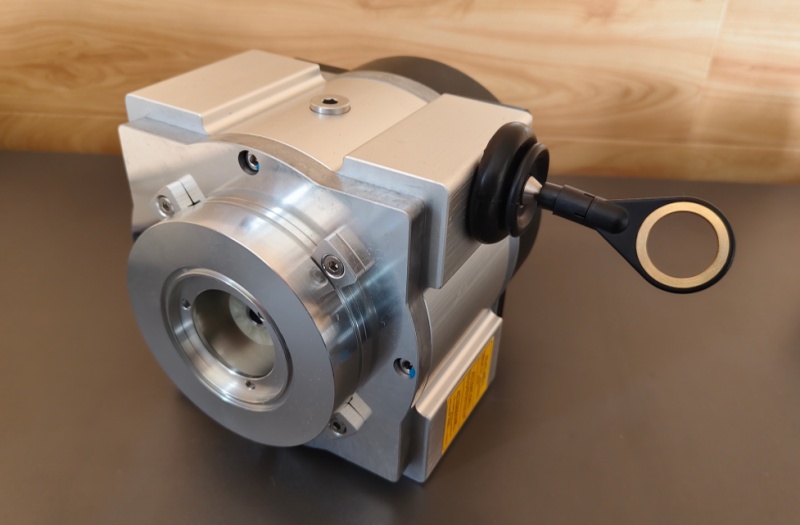
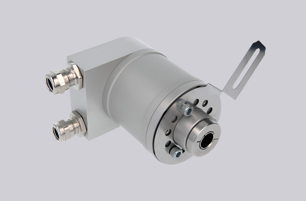
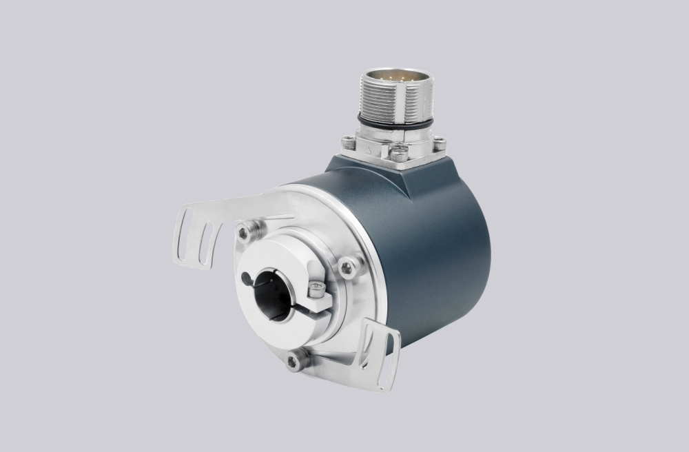
From the mechanical coding of this variant, the unit uses a 12 mm through hollow shaft, a long spring element mounting style, and a removable bus terminal cover with cable gland M16. This combination is important for installations where shaft fit, anti-rotation restraint, and cable entry direction all need to remain aligned with the field arrangement already in service. The sensing principle is optical / magnetic, which supports absolute position feedback in industrial motion and rotating equipment applications.
Industrial Integration Considerations
For retrofit work, the most important point on this model is not only the communication protocol but also the complete installation logic around the hollow shaft and mounting hardware. Because this version is built around a large through hollow shaft platform, shaft diameter, fit condition, clamping practice, and spring element geometry should be preserved during engineering review. In this coded version, the shaft size is 12 mm H7, and the flange code indicates the long spring element arrangement.
On the electrical side, the encoder operates on 10 ... 30 V DC and communicates via PROFIBUS DP with baud rates up to 12 Mbit/s. The documentation also indicates programmable direction of rotation, scaling factor, preset value, and diagnostics mode, together with DIP-switch or rotary-switch based device addressing, depending on the described interface functions in the datasheet text. For field replacement projects, these items matter because controller-side expectations often depend on the original data structure, addressing practice, and diagnostic behavior already commissioned in the machine.
Environmental suitability also plays a role in installation continuity. The encoder platform is rated IP65, with a working temperature range of -10°C to +70°C, shock resistance to EN 60068-2-27, and vibration resistance to EN 60068-2-6. These characteristics make the model suitable for industrial feedback applications where sealing, vibration endurance, and stable communication are required at the same time.
Custom Compatible Encoder Solution
A custom compatible encoder solution for 8.9080.3131.3001 should focus on preserving four core engineering points: PROFIBUS DP communication behavior, multiturn absolute data structure, 12 mm through hollow shaft installation, and the long spring element mounting concept. In many field projects, replacement success depends less on nominal appearance and more on whether the encoder can integrate with the original shaft, bus topology, addressing scheme, and mechanical restraint arrangement without creating secondary modification work.
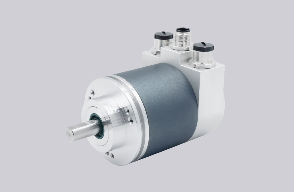
For this reason, a compatible solution can be engineered to match the original interface category, voltage range, bus profile class, scalable resolution logic, and cable-entry style. The coded configuration also indicates that the original version uses the cable gland terminal cover rather than the M12 connector version, so this detail should be maintained if the existing machine wiring layout depends on terminal-box style field connection. Where coded options or site-specific settings are involved, the final field configuration should be confirmed during engineering review so that installation, commissioning, and bus parameterization remain consistent with the original application.
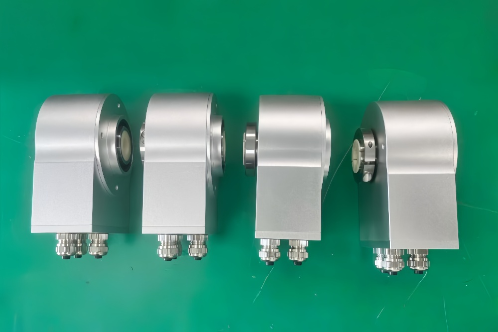
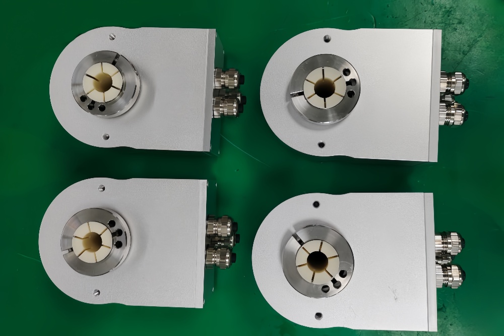
Custom Solution Photos
Lead Time and Custom Development
Typical production lead time: 30 working days.
For custom development, the main checkpoints should include shaft bore size, fixing style, terminal or cable entry arrangement, PROFIBUS communication expectations, scaling requirements, and addressing logic. The source documentation shows that this encoder family supports programmable rotation direction, preset value, resolution scaling, and diagnostics mode, so a compatible engineering solution should be reviewed not only from the mechanical side but also from the bus integration side. This is especially important in maintenance and upgrade projects where the original control program already expects a defined encoder profile class and absolute position format.
Typical Technical Parameters
| Parameter | Specification |
|---|---|
| Encoder Type | Multiturn absolute encoder |
| Model | 8.9080.3131.3001 |
| Interface | PROFIBUS DP |
| Protocol Profile | Encoder profile class 2 |
| Physical Layer | RS485 |
| Supply Voltage | 10 ... 30 V DC |
| Resolution Singleturn | 1 ... 8192 steps, scalable |
| Multiturn Capability | 1 ... 4096 revolutions, scalable |
| Max Overall Resolution | 25 bit |
| Code Type | Binary |
| Baud Rate | Max. 12 Mbit/s |
| Address Setting | Adjustable by DIP-switches / switch-based addressing as stated in datasheet |
| Programmable Functions | Direction of rotation, scaling factor, preset value, diagnostics mode |
| Shaft Type | Through hollow shaft |
| Bore Size | 12 mm H7 |
| Mounting Style | Spring element, long |
| Connection Type | Removable bus terminal cover with cable gland M16 |
| Protection Rating | IP65 |
| Operating Temperature | -10°C ... +70°C |
| Max. Speed | 6000 min⁻¹ max., 3000 min⁻¹ continuous |
| Sensing Principle | Optical / magnetic |
| Shock Resistance | 2500 m/s², 6 ms |
| Vibration Resistance | 100 m/s², 10 ... 2000 Hz |