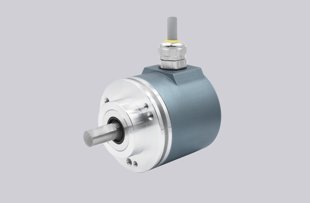
A customized replacement solution is available for DAF66-12B11, developed to match the original 4–20 mA absolute output and shaft interface while supporting application-specific adjustments where required. The replacement encoder is engineered to align with existing mechanical layouts and electrical parameters, allowing direct installation without changes to control systems or mounting structures. By adopting a flexible production approach, typical delivery can be achieved within approximately 15 working days, helping users reduce downtime and sourcing pressure while enabling small-batch OEM customization.
From a technical perspective, the encoder provides stable current-loop transmission suitable for long cable distances and electrically demanding environments. Its absolute position feedback remains consistent under vibration and temperature variation, supporting reliable operation in automation equipment, material handling systems, and industrial motion control applications where long-term signal integrity and predictable performance are essential.
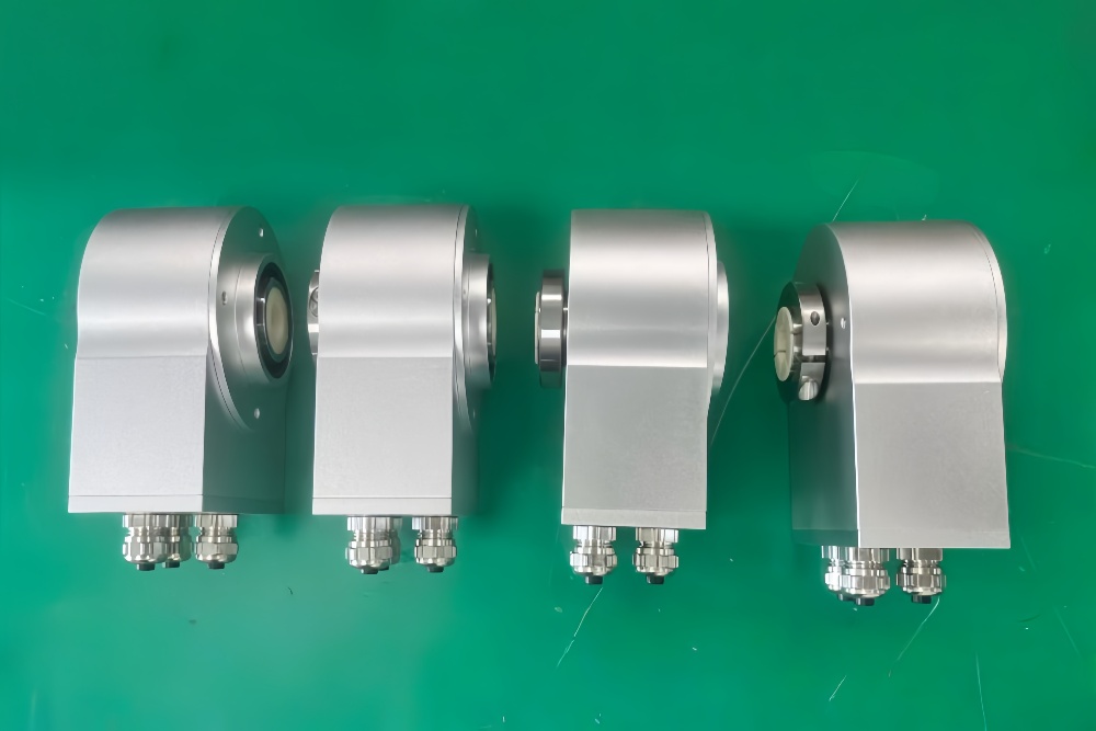
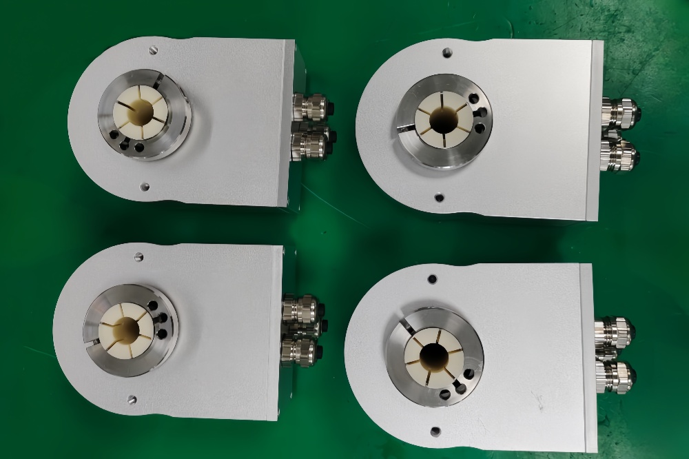
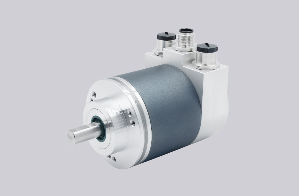
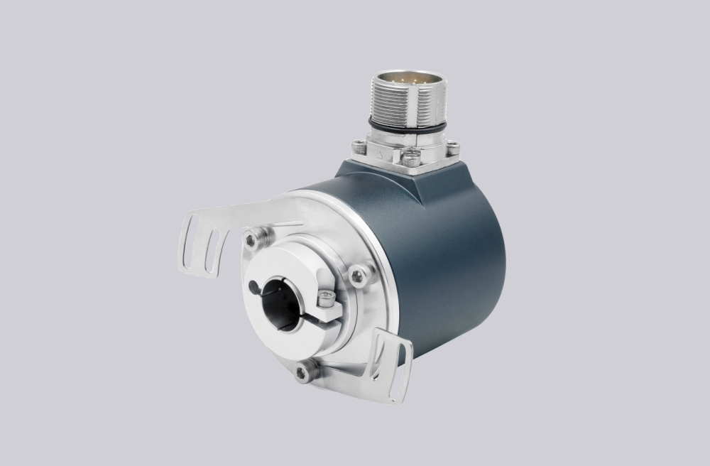
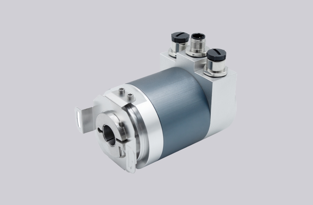
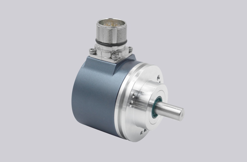
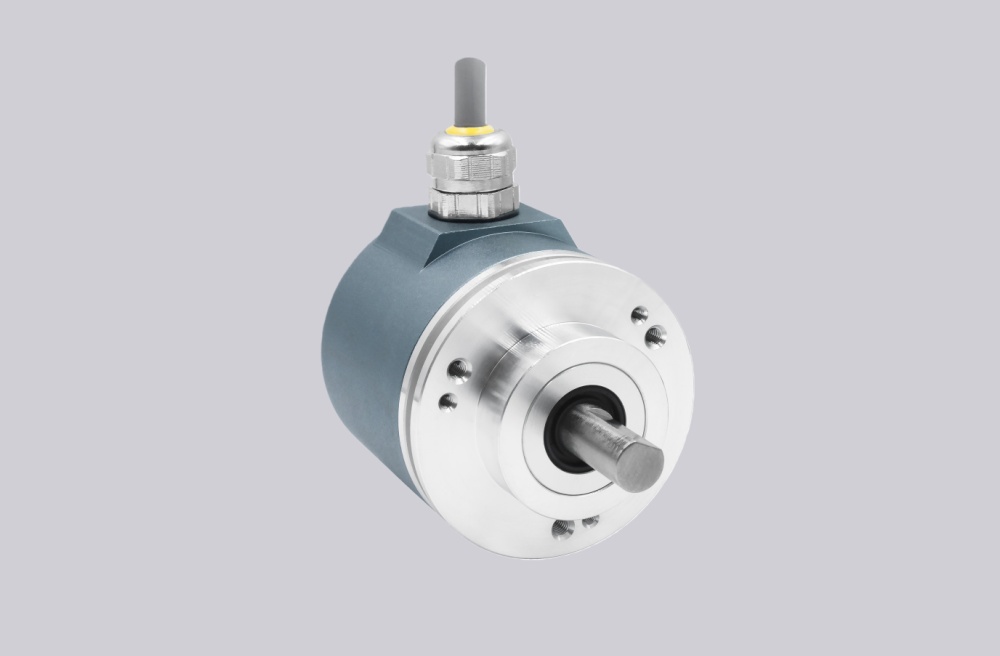
Reference Images
Electrical data
| Parameter | Value |
| Valid for all versions | Unless otherwise stated |
| Sensor system: | GaAIAs diode, photo-transistor array, precision comparator |
| Setting cycles EEPROM: | ≥10^6 |
| Multifunctional inputs (MFP): | Depending on adjusting mode (signal input E6) |
| Memory circuit (latch): | Through MFP |
| Disc coding: | Gray code |
| Signal sense: | CW or CCW (signal input E6) |
| Supply voltage range V_s: | +20 to +26 VDC, 15±0.5VDC(optional) |
| Supply current I_s: | 80 mA typ. / 120 mA max. (when output current = 0) |
| Linearity: | 0.025% typ. / 0.05% max. (+2 LSB), 12 Bit monotory warranted |
| Temperature drift: | 0.0015% / K typ. |
| Current output | |
| Accuracy | |
| at starting point 0 mA: | 0 mA ±5 μA typ. / ±15 μA max. |
| at end point 4 mA: | 4 mA ±5 μA typ. / ±15 μA max. |
| Load resistance: | 0 to 500Ω at V_s = 20 to 26 VDC, 0 to 1000Ω at V_s = 22 to 26 VDC |
| Voltage output | |
| Accuracy | |
| at starting point 0 V: | 0 V ±2.5 mV typ. / ±7.5 mV max. |
| at end point 10 V: | 10 V ±2.5 mV typ. / ±7.5 mV max. |
| Output current: | 5 mA max. When load resistance > 2 kΩ (short circuit proof) |