A project-specific compatible encoder solution can be arranged for 8.9080.1132.3001 in maintenance, retrofit, replacement, and upgrade projects where the original encoder uses no mounting aid, a 12 mm through hollow shaft, and M12 connectorized PROFIBUS wiring. Typical production lead time: 15 working days. This variant is especially dependent on the surrounding machine structure because the encoder code indicates that mounting aid is not included as part of the encoder-side configuration.
Technical Overview of the 8.9080.1132.3001 Encoder
This model uses the same multiturn absolute PROFIBUS DP platform as the rest of the family, with RS485 communication, binary code, scalable singleturn and multiturn resolution, and programmable direction, scaling, preset, and diagnostics functions. It operates on 10 ... 30 V DC and is designed for industrial environments requiring protected absolute feedback devices.
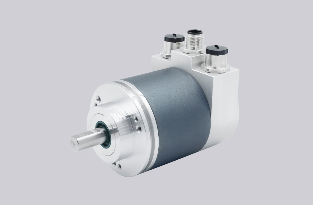
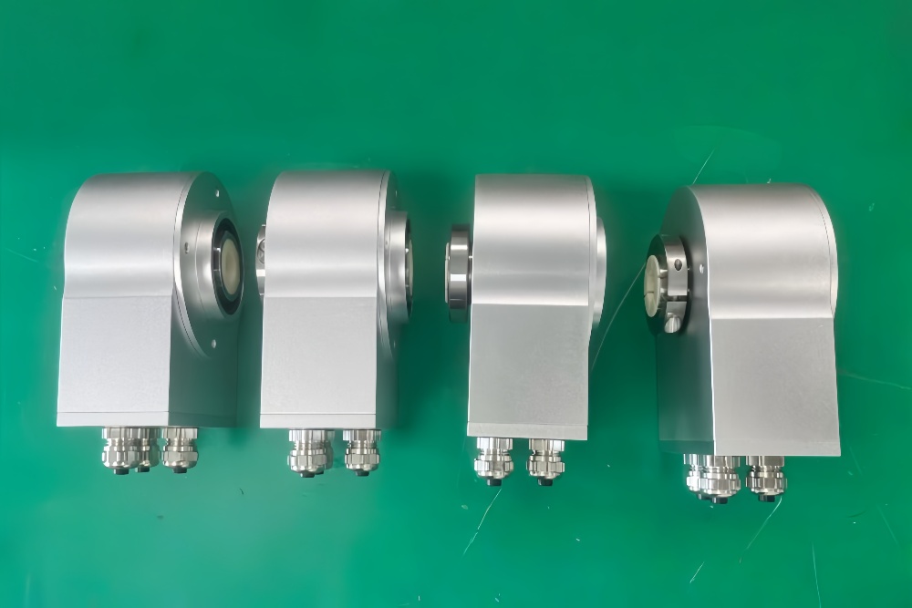
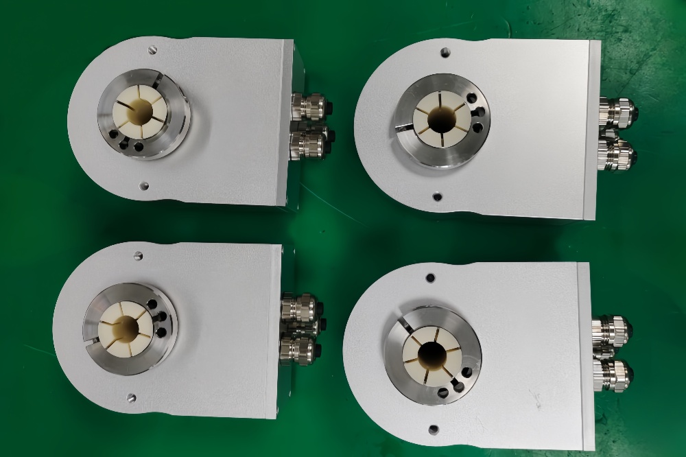
Its order code resolves to flange type 1, shaft code 1, and connection code 2. That means without mounting aid, with a 12 mm H7 through hollow shaft, and with 3 x M12 connectors. This combination is suited to applications where the machine provides its own restraint or bracket concept and where connectorized bus access is preferred.
Industrial Integration Considerations
Because this version is supplied without mounting aid, integration responsibility shifts toward the machine-side hardware. During retrofit support, external restraint geometry, anti-rotation strategy, and connector access must all be reviewed together. A nominally correct encoder body alone is not enough if the installation environment depends on application-specific support parts.
The 3 x M12 connector layout can simplify field service when the original cabling is built around pre-assembled cords, but connector clearance and plug routing still need to be checked carefully in compact spaces. This is especially relevant on smaller bore versions that may be installed close to neighboring hardware.
Custom Compatible Encoder Solution
For 8.9080.1132.3001, a compatible replacement solution should preserve the 12 mm through hollow shaft, no-mounting-aid configuration basis, and 3 x M12 connector layout while maintaining the original PROFIBUS DP class 2 communication behavior. This supports applications where the machine builder’s own hardware defines the actual mounting method.
Any original bus-side settings related to address, scaling, or preset handling should be confirmed during engineering matching so the new encoder can be commissioned with minimal disruption.
Custom Solution Photos
Lead Time and Custom Development
Typical production lead time: 15 working days.
Engineering review should focus on external restraint method, shaft fit, connector routing, and system-side PROFIBUS configuration. This model is best handled as a machine-integrated variant rather than a purely standalone encoder replacement.
Typical Technical Parameters
| Parameter | Specification |
|---|---|
| Encoder Type | Multiturn absolute encoder |
| Model | 8.9080.1132.3001 |
| Interface | PROFIBUS DP |
| Protocol Profile | Class 2 |
| Physical Layer | RS485 |
| Supply Voltage | 10 ... 30 V DC |
| Resolution Singleturn | 1 ... 8192, scalable |
| Multiturn Capability | 1 ... 4096, scalable |
| Max Overall Resolution | 25 bit |
| Code Type | Binary |
| Shaft Type | Through hollow shaft |
| Bore Size | 12 mm H7 |
| Mounting Style | Without mounting aid |
| Connection Type | 3 x M12 connector |
| Protection Rating | IP65 |
| Operating Temperature | -10°C ... +70°C |
| Max. Speed | 6000 min⁻¹ max., 3000 min⁻¹ continuous |