The 8.9080.4132.3001 encoder can be supported through a custom compatible solution for replacement, maintenance, retrofit, and upgrade projects that require a flange-mounted, connectorized PROFIBUS encoder. This coded version combines a 12 mm through hollow shaft with a mounting flange and 3 x M12 connectors. Typical production lead time: 15 working days. The engineering value lies in retaining flange-side mechanical reference points while preserving connector-based fieldbus wiring practice.
Technical Overview of the 8.9080.4132.3001 Encoder
This model is part of a multiturn absolute encoder family using PROFIBUS DP and RS485 communication technology. The platform offers binary code, scalable singleturn and multiturn resolution, and programmable functions including direction, preset, diagnostics, and scaling. These characteristics make it adaptable to established automation systems where both hardware and bus parameter behavior must remain consistent.
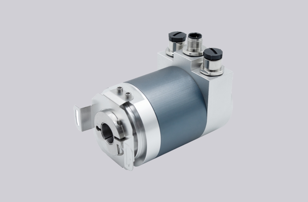
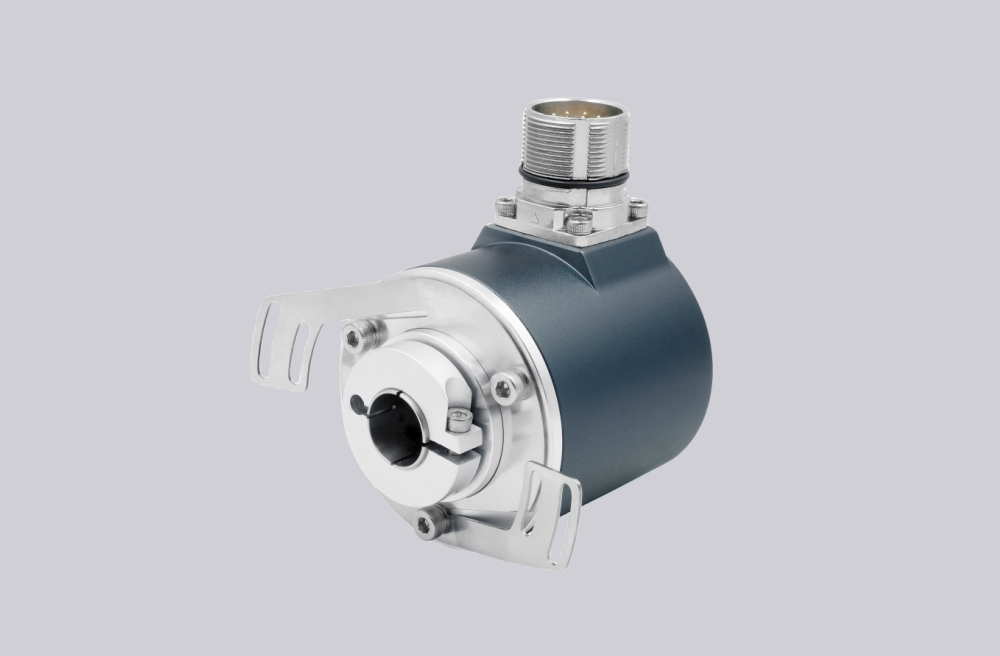
In the ordering structure, flange code 4 means mounting flange, shaft code 1 means 12 mm H7 through hollow shaft, and connection code 2 means 3 x M12 connector. This creates a compact-bore flange version with connectorized wiring, which can be advantageous where service access and repeatable cable routing are required.
Industrial Integration Considerations
A 12 mm flange-mounted version often appears in compact drive systems or rotating assemblies where installation space is more constrained. For retrofit continuity, flange position, shaft engagement, and connector access should all be reviewed together. A replacement that matches only one of those aspects can still create avoidable field work.
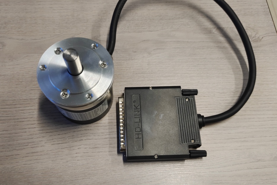
Because this model uses M12 interfaces for bus in, bus out, and power, cable clearance and plug orientation may be just as important as shaft fit in practice. This is especially true when the encoder is installed near guarding, motor housings, or bracketry that limits connector bend space.
Custom Compatible Encoder Solution
A custom compatible encoder solution for 8.9080.4132.3001 should retain the 12 mm bore, mounting flange geometry, and 3 x M12 connector arrangement while preserving PROFIBUS DP class 2 communication and scalable absolute position behavior. This provides both electrical and mechanical continuity for maintenance support projects.
Where the original installation uses preset values, direction reversal, or custom scaling, those details should be captured during engineering review so the compatible solution remains aligned with the existing control configuration.
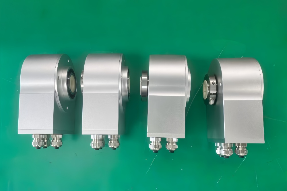
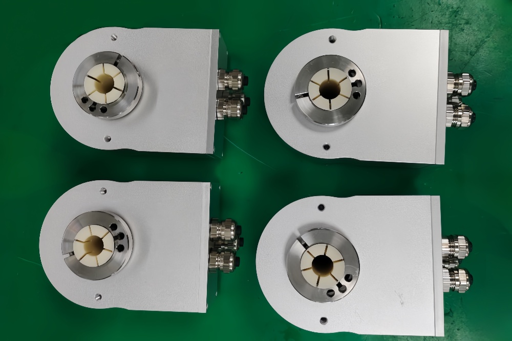
Custom Solution Photos
Lead Time and Custom Development
Typical production lead time: 15 working days.
Engineering review should verify flange reference dimensions, shaft tolerance, connector access, and bus parameterization. This model is especially sensitive to physical cable routing because of its M12 connection layout.
Typical Technical Parameters
| Parameter | Specification |
|---|---|
| Encoder Type | Multiturn absolute encoder |
| Model | 8.9080.4132.3001 |
| Interface | PROFIBUS DP |
| Protocol Profile | Class 2 |
| Physical Layer | RS485 |
| Supply Voltage | 10 ... 30 V DC |
| Resolution Singleturn | 1 ... 8192, scalable |
| Multiturn Capability | 1 ... 4096, scalable |
| Max Overall Resolution | 25 bit |
| Code Type | Binary |
| Shaft Type | Through hollow shaft |
| Bore Size | 12 mm H7 |
| Mounting Style | Mounting flange |
| Connection Type | 3 x M12 connector |
| Protection Rating | IP65 |
| Operating Temperature | -10°C ... +70°C |
| Max. Speed | 6000 min⁻¹ max., 3000 min⁻¹ continuous |