A project-specific compatible encoder solution can be arranged for 8.9080.1331.3001 when the machine uses a 20 mm through hollow shaft encoder without mounting aid and with cable gland field connection. This variant supports maintenance, retrofit, replacement, and upgrade projects where the original installation concept needs to be preserved with minimal system disturbance. Typical production lead time: 30 working days. The engineering emphasis for this model is straightforward shaft continuity and original housing arrangement retention.
Technical Overview of the 8.9080.1331.3001 Encoder
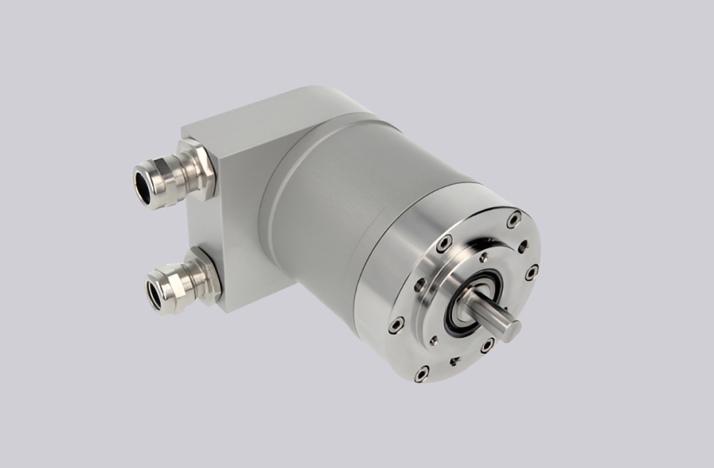
The 8.9080.1331.3001 is a multiturn absolute encoder with PROFIBUS DP interface, RS485 communication, binary code, and scalable resolution architecture up to 25 bits overall. The platform supports programmable parameters including rotation direction, preset value, diagnostics mode, and scaling factor handling. It also operates from 10 ... 30 V DC and is rated IP65 with industrial shock and vibration resistance.
Its specific code identifies flange type 1, meaning without mounting aid, together with a 20 mm H7 through hollow shaft and cable gland M16 connection cover. This type of configuration is relevant where the machine already provides its own mechanical restraint logic rather than relying on spring elements or tether arms included in the encoder assembly.
Industrial Integration Considerations
When a version is specified without mounting aid, the surrounding machine design usually carries more responsibility for encoder stabilization and anti-rotation control. For replacement projects, that means the original bracketry, clamping method, or external restraint concept should be reviewed carefully during engineering matching. The encoder itself may be standardized, but the installation method is often application-specific.
The 20 mm hollow shaft and cable gland connection remain the two most obvious field compatibility points. If the existing installation relies on direct cable entry, internal termination, and enclosure-level sealing, maintaining that arrangement generally reduces site work during retrofit support.
Custom Compatible Encoder Solution
For 8.9080.1331.3001, a custom compatible encoder solution should retain the 20 mm through hollow shaft, no-mounting-aid configuration basis, and cable gland terminal cover while preserving the original PROFIBUS DP class 2 communication platform. This approach is particularly useful where the machine builder’s own mounting structure is part of the installed design.
The final coded configuration should be checked together with the original field restraint method and controller-side parameter settings so the compatible solution remains practical for installation continuity.
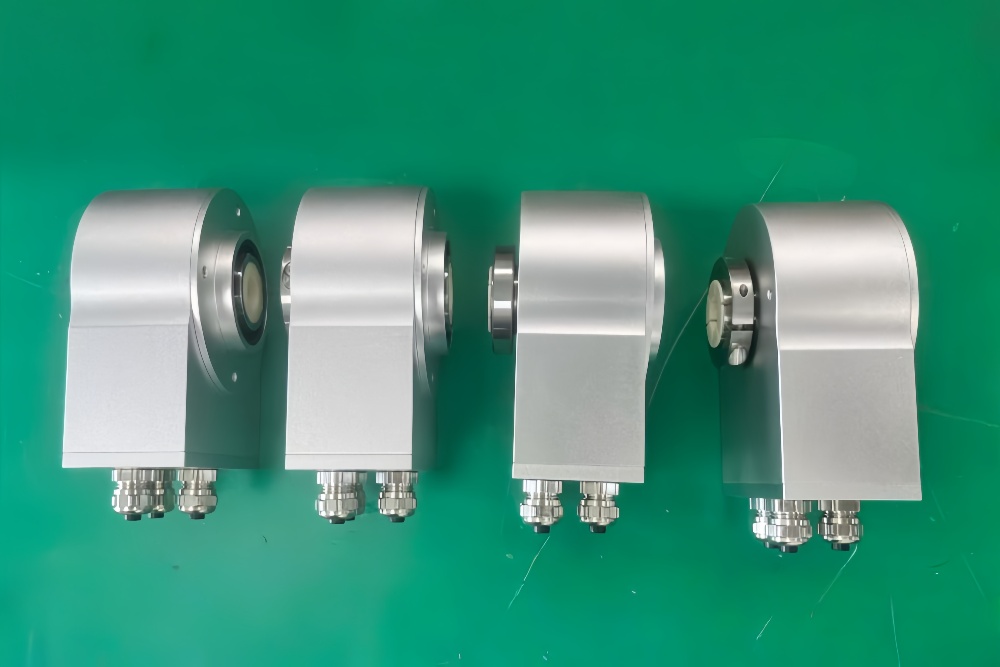
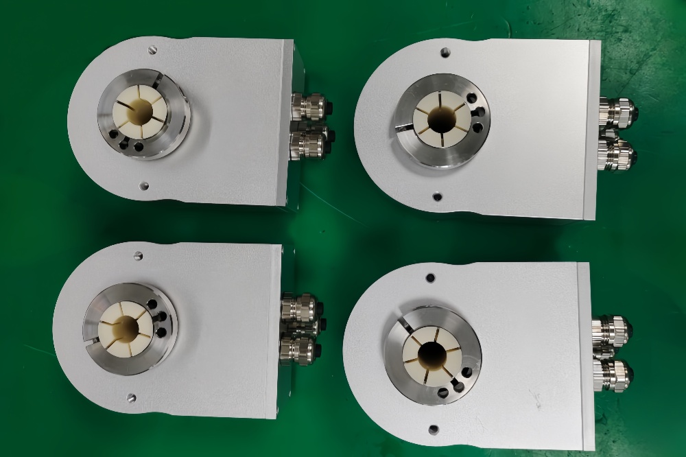
Custom Solution Photos
Lead Time and Custom Development
Typical production lead time: 30 working days.
Engineering review should focus on shaft fit, housing stabilization method, cable entry practice, and fieldbus configuration requirements. This model should not be evaluated only by the encoder body, because surrounding machine hardware may define much of the true compatibility.
Typical Technical Parameters
| Parameter | Specification |
|---|---|
| Encoder Type | Multiturn absolute encoder |
| Model | 8.9080.1331.3001 |
| Interface | PROFIBUS DP |
| Protocol Profile | Class 2 |
| Physical Layer | RS485 |
| Supply Voltage | 10 ... 30 V DC |
| Resolution Singleturn | 1 ... 8192, scalable |
| Multiturn Capability | 1 ... 4096, scalable |
| Max Overall Resolution | 25 bit |
| Code Type | Binary |
| Shaft Type | Through hollow shaft |
| Bore Size | 20 mm H7 |
| Mounting Style | Without mounting aid |
| Connection Type | Removable bus terminal cover with cable gland M16 |
| Protection Rating | IP65 |
| Operating Temperature | -10°C ... +70°C |
| Max. Speed | 6000 min⁻¹ max., 3000 min⁻¹ continuous |