M6-5S3XH51-T003 Incremental Encoder Replacement
We provide a customized replacement solution for the M6-5S3XH51-T003 incremental encoder. The replacement fully matches the original in mechanical dimensions, shaft configuration, and electrical output, ensuring seamless integration into existing industrial systems. It is suitable for motion control, automated machinery, and conveyor applications. This solution delivers reliable performance, long-term operational stability, and maintenance-friendly deployment, effectively addressing procurement challenges while offering a practical and stable alternative for industrial use.
ATEX and IECEx Certified Encoder
Explosion Protected/ATEX & IECEx Zone 1 Rated/Up to 1200 PPR/Severe Mill Duty/Immune to dust, water, oil, etc.
Does not require intrinsic safety barriers/Withstands extreme shock and vibration/Protected against wiring errors
Excellent for oil and gas drilling applications
Introduction
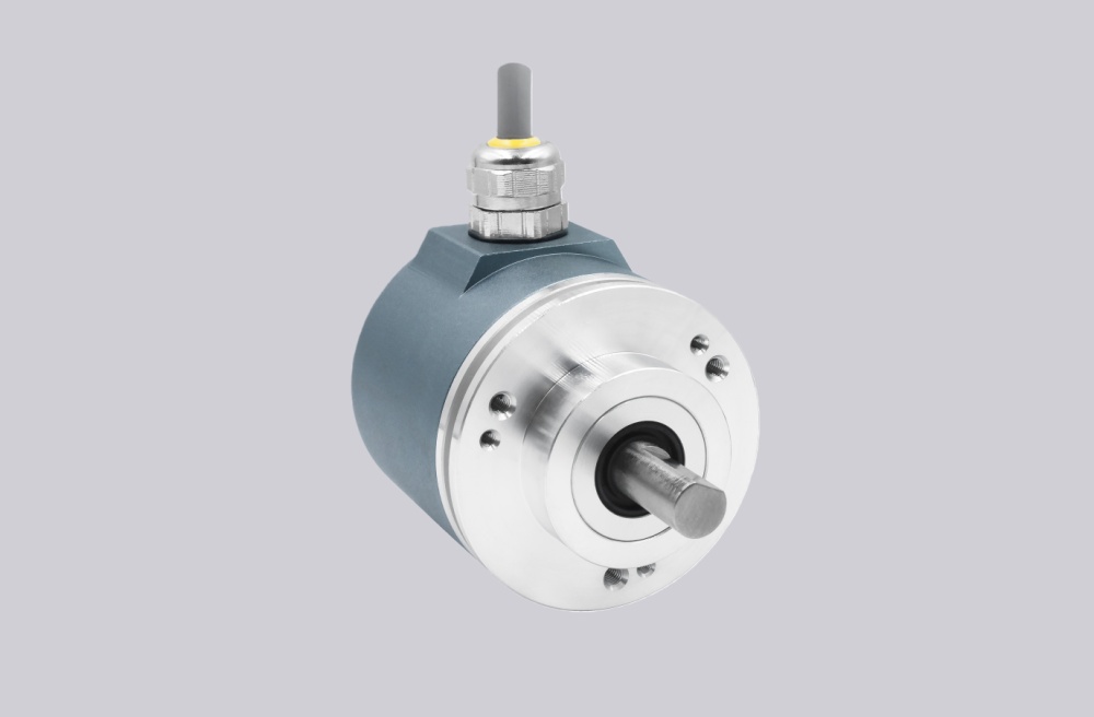
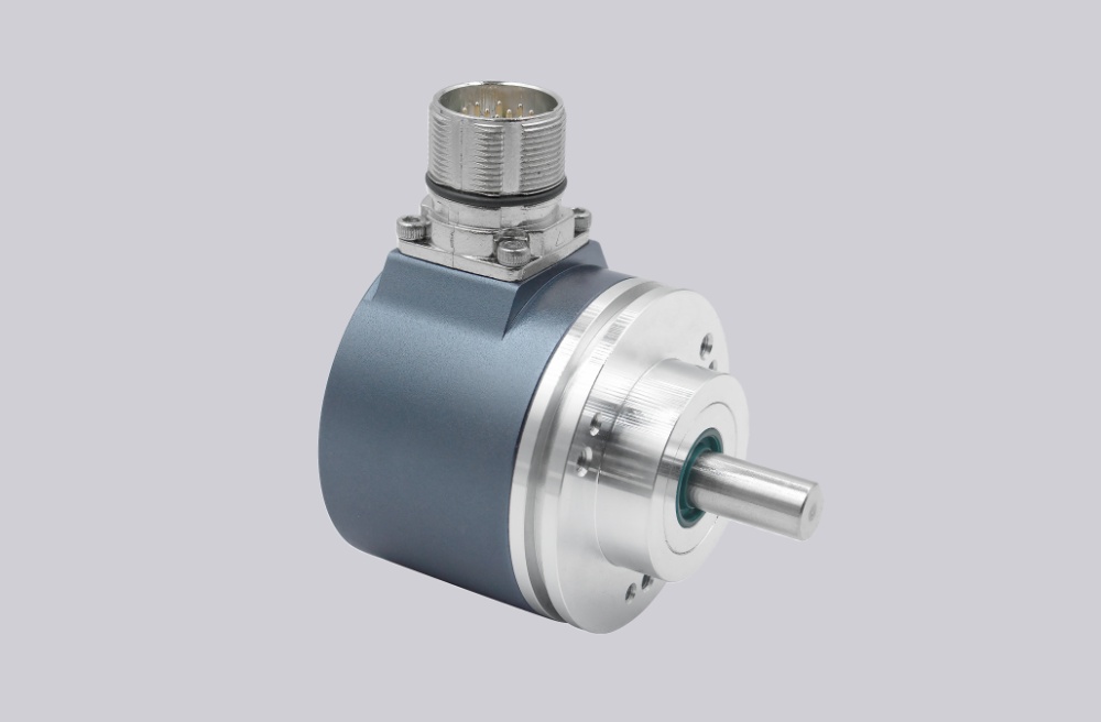
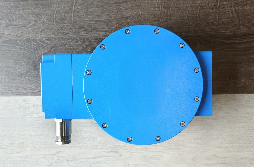
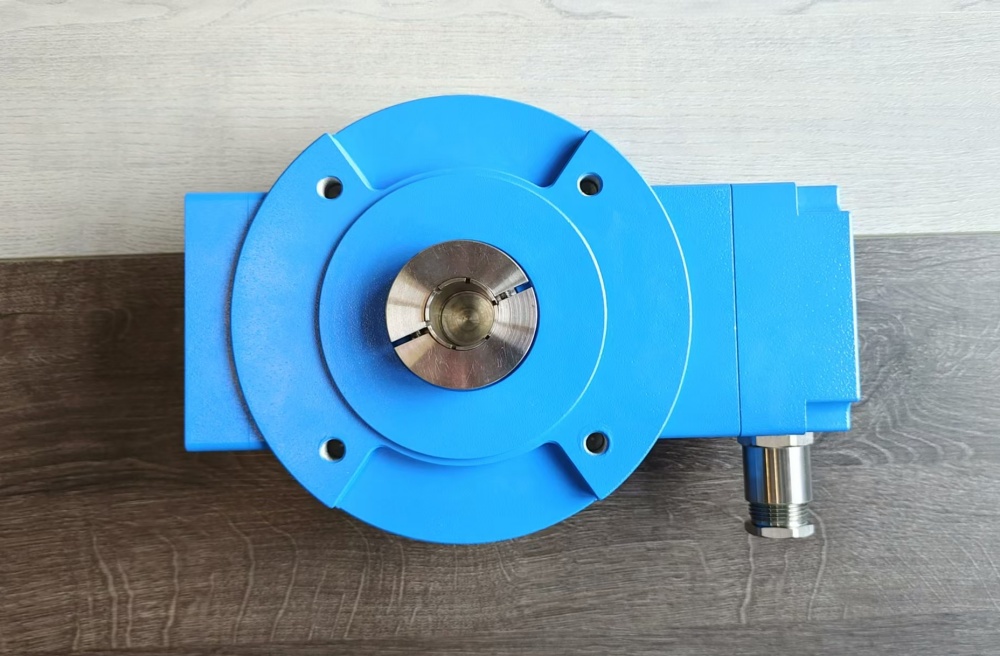
Avtron M6C explosion protected ATEX and IECEx rated severe mill duty rotary encoders are designed for direct mounting on motor or load shafts, from 1" to 1 1/8" [25-30mm].
The M6C is an updated model which directly replaces the M6 encoder, and M6C adds IECEx certification. No barrier or isolator is required-mount M6C directly in any ATEX or IECEx Zone 1 application.
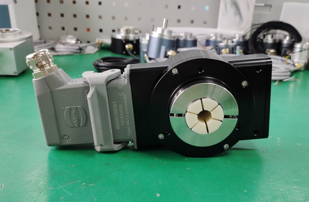
Why take a chance with weak optical encoders on your drilling rig? The M6C features Avtron Encoders' rugged magnetic sensor and solid metal rotor technology. Our shatterproof, moisture proof systems ensure your application has maximum uptime. The hollow shaft (tethered) models offer direct mounting on shafts from 1" to 1 1/8", without flanges, reducers, couplings, or other hardware. No rework is needed; just mount the encoder directly on the shaft, and secure the tether arm. The heavy duty bearings withstand runout and vibration that destroy lesser encoders.
M6C also includes a complete wiring protection system--it can survive all types of wiring errors and drive signals down the longest cables.
For more information on keeping your rotary encoders working in oil and gas applications, visit our oil and gas blog.
We believe explosion protected encoders should also be ready to withstand the rough drilling environment. Try the M6C today!
Parameters
Operating Power: Volts: 5-24 VDC; Current: 120mA, no load
Output Format: A, /A, B, /B; Optional Marker Z, /Z
Frequency Range: 0 to 250 kHz @ 6 V & 1 meter cable
PPR: 240-1200
Speed: 5000 RPM Max. Std.
Temperature: 80°C to -40°C (-40°C optional, -20°C standard)
Chemical: Polyurethane enamel paint protects against salt spray, mild acids, and bases
Enclosure Rating: IP66
Explosion Protection:
ATEX 0539 II 2 G Ex d e IIB T4 Gb
(Tamb = -40/-20°C to +80°C)
IECEx Ex d e IIB T4 Gb
(Tamb = -40/-20°C to +80°C)
Weight: 18 lbs. / 8kg.
All dimensions are in inches [millimeters].
Specifications and features are subject to change without notic