For systems using the FG40KK-2500G-90G-NG-S, a custom compatible encoder solution can be engineered for maintenance support, retrofit execution, replacement planning, and upgrade work. Where the installed machine depends on a dual-terminal-box encoder with integrated overspeed monitoring, the compatible version can be developed around the original signal logic and switching function, with a typical production lead time of 30 working days.
Technical Overview of the FG40KK-2500G-90G-NG-S Encoder
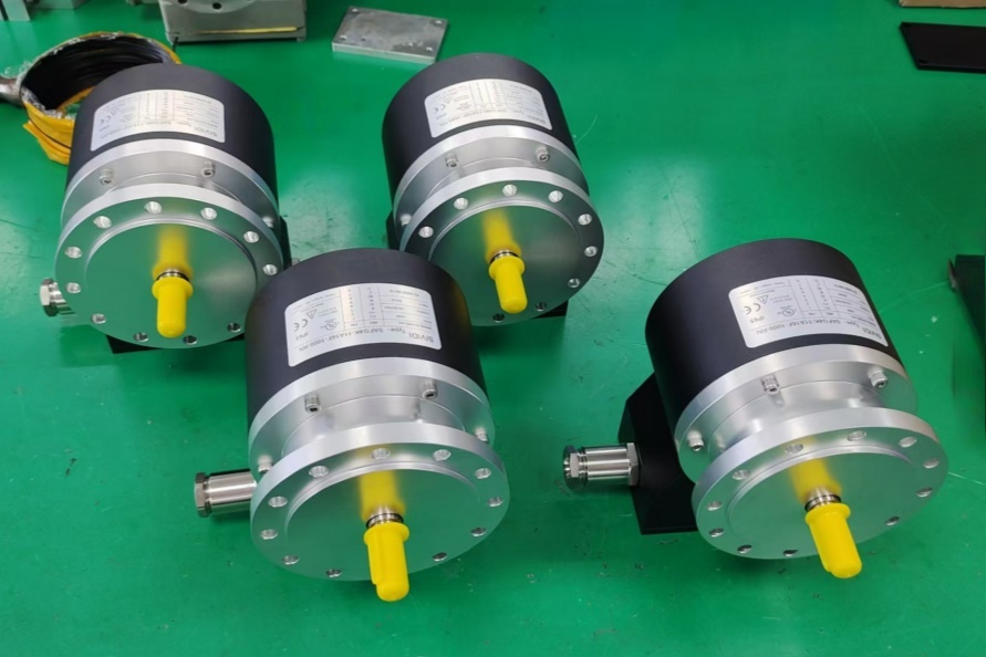
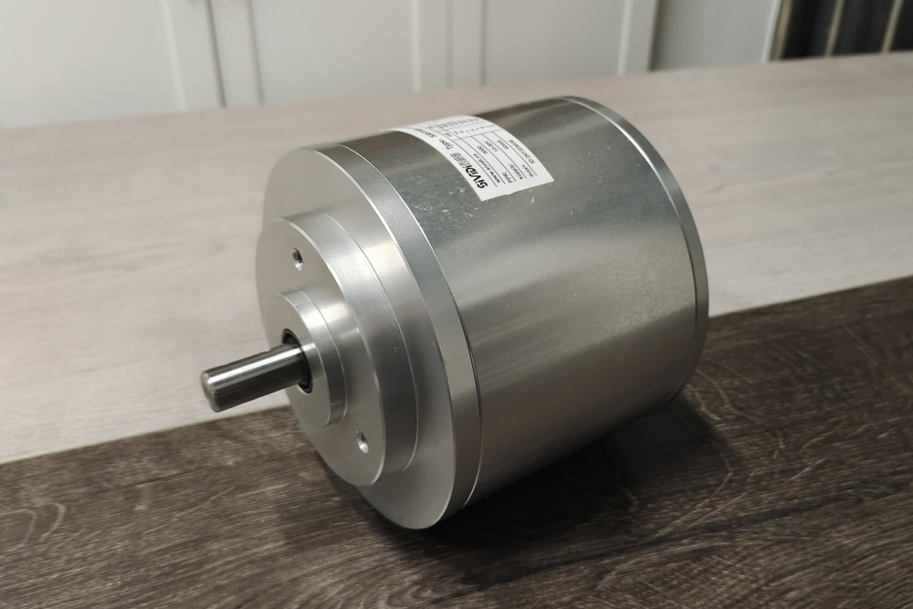
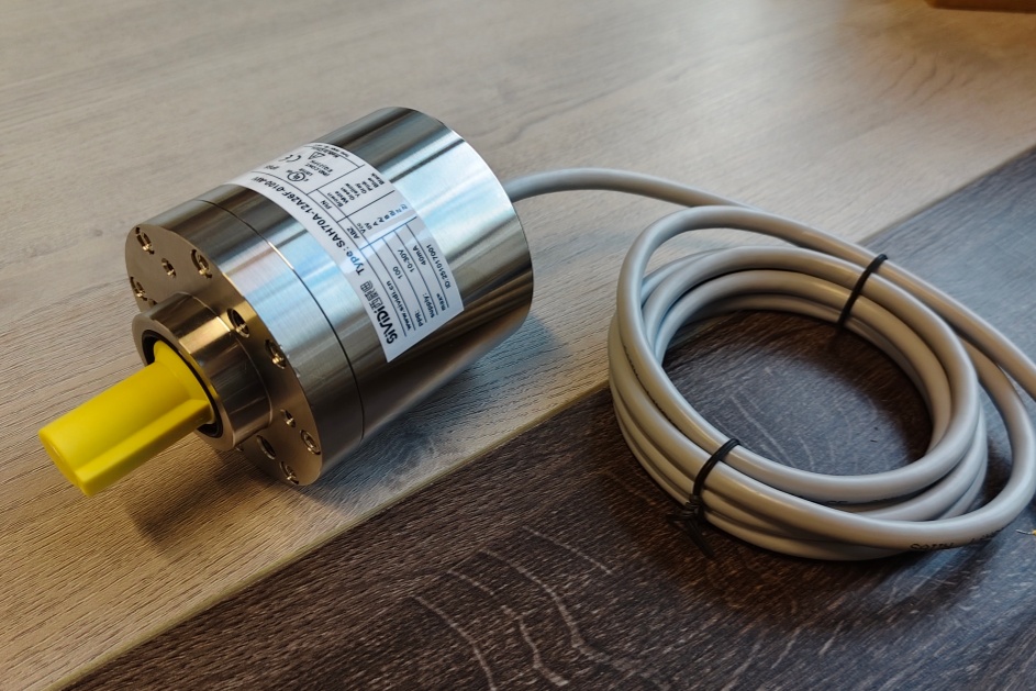
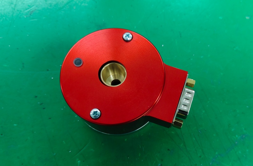
The FG40KK-2500G-90G-NG-S is an incremental encoder for rotary motion measurement in industrial drive and feedback systems. The latest FG 40 manual confirms that 2500 is one of the standard pulse rates in the series and that the electrical platform supports 12–30 V DC supply, a current-limited, short-circuit proof push-pull line driver with integrated impedance adaptation for 30 to 140 Ω lines, standard HTL output, optional 5 V TTL / RS422-compatible output, and a maximum frequency of 200 kHz.
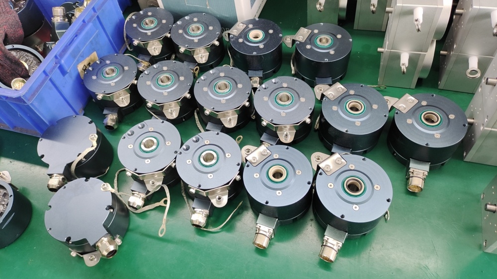
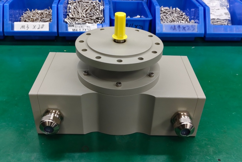
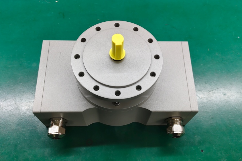
In this model code, 2500G defines a 2500 ppr configuration, while 90G identifies the square-wave output structure with channel 0° (A) and channel 90° (B), each with inverted signals. The NG code adds a mechanically defined reference pulse with inverted signal. What clearly distinguishes this model from the earlier non-S variants is Option S, which the manual defines as an electronic overspeed switch with two independently programmable switching points. The type-code section also states that KK means 2 terminal boxes, used as a redundant version or together with Option S, so this model should be treated as both a feedback encoder and a speed-monitoring device.
Industrial Integration Considerations
For this version, integration work should not focus only on pulse count and output level. A 2500 ppr signal structure must still be checked against the receiving controller, counter module, or drive input for pulse-processing capability, shielding quality, and reference-pulse handling, but the project review also has to confirm how the installed system uses the overspeed switch. In practical terms, the switching outputs may be tied into alarm logic, interlocks, shutdown behavior, or limit-speed supervision rather than simple feedback evaluation.
The FG 40 manual also provides practical installation guidance that becomes more important when both feedback and switching functions are involved. Installation and commissioning must be carried out by skilled technical staff only, and a hammer or similar tool must not be used because of the risk of damage to the bearings or coupling. The manual further recommends using threadlocker on fastening screws and confirms that cable shielding can be connected directly to the housing through the cable gland or alternatively via the specified shielding arrangement at the terminal connection. These details matter because switching stability and incremental signal quality both depend on disciplined installation practice.
Custom Compatible Encoder Solution
For the FG40KK-2500G-90G-NG-S, a custom compatible encoder solution can be configured to match the original machine interface as closely as possible. The compatible design can be aligned with the required 2500 ppr signal structure, the two-terminal-box arrangement, the defined reference-pulse logic, the required output level, and the integrated Option S switching function so that changes to the surrounding machine remain limited.
This is particularly useful where the installed machine already uses the encoder as part of both the feedback chain and the protective speed-monitoring concept. In those cases, the practical goal is not only to preserve incremental output behavior, but also to maintain switching logic, field wiring structure, and service continuity during replacement.
Lead Time and Custom Development
Typical production lead time: 30 working days.
Before production, the engineering review should confirm the pulse count, output type, supply voltage, reference-pulse requirement, terminal-box arrangement, installation dimensions, controller input expectations, and the required switching behavior of Option S. The programmed switching points, wiring concept, and installation conditions should also be checked in advance so the compatible solution can be matched to the actual operating environment.
Typical Technical Parameters
| Parameter | Specification |
|---|---|
| Encoder Type | Incremental encoder |
| Resolution | 2500 ppr |
| Output Type | Square-wave incremental output with overspeed switch function |
| Signal Format | 0° / 90° channels with inverted signals, reference pulse with inverted signal |
| Supply Voltage | 12–30 V DC |
| Output Level | HTL, optional 5 V TTL / RS422-compatible |
| Output Driver | Current-limited, short-circuit proof push-pull line driver |
| Line Adaptation | Integrated impedance adaptation for 30 to 140 Ω lines |
| Max Frequency | 200 kHz |
| Duty Cycle | 1:1 ±3% for standard pulse rates |
| Phase Displacement | 90° ±3% for standard pulse rates |
| Connection Type | Terminal box connection |
| Terminal Box Arrangement | KK version, 2 terminal boxes |
| Monitoring Function | Electronic overspeed switch with two independently programmable switching points |
| Application Orientation | Maintenance, retrofit, replacement, upgrade |