A custom compatible encoder solution can be provided for the FGH6KK-2000G-90G-NG-J/50P for maintenance, retrofit, replacement, and upgrade projects. This model can be supported with a project-matched compatible solution designed around the existing hollow-shaft installation, signal structure, and field wiring arrangement, with a typical lead time of 30 working days.
Technical Overview of the FGH6KK-2000G-90G-NG-J/50P Encoder
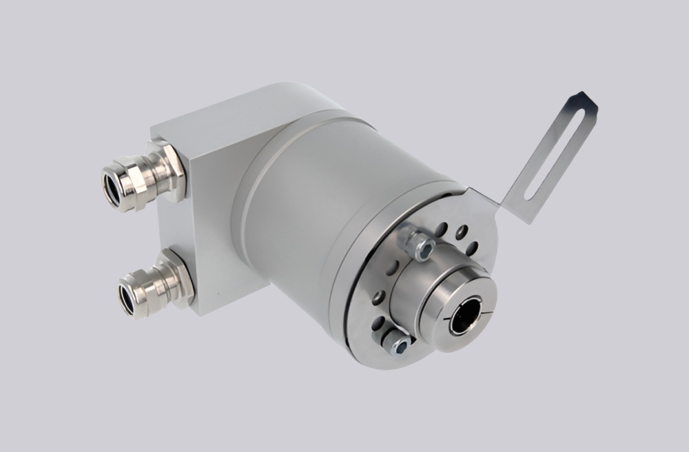
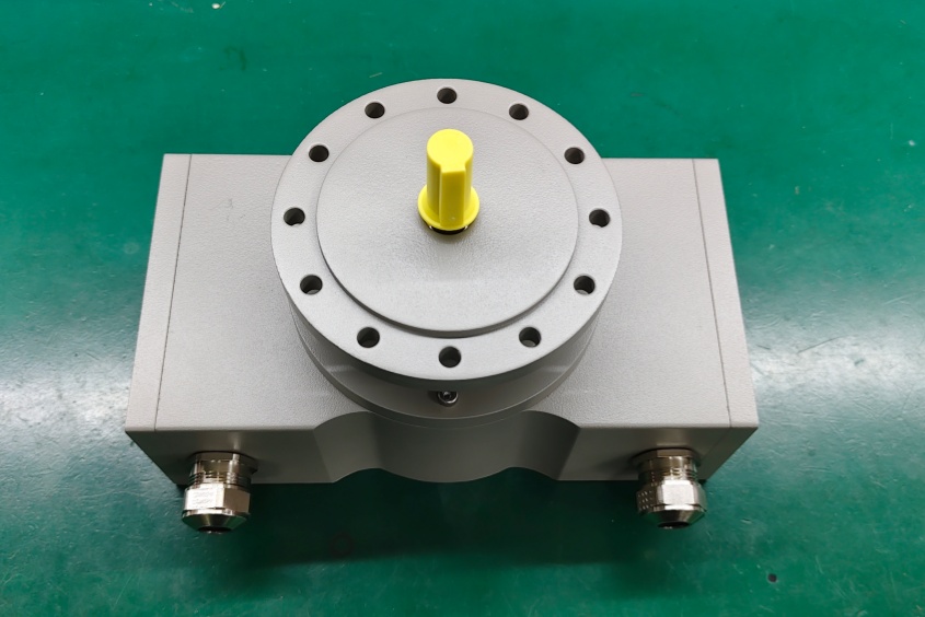
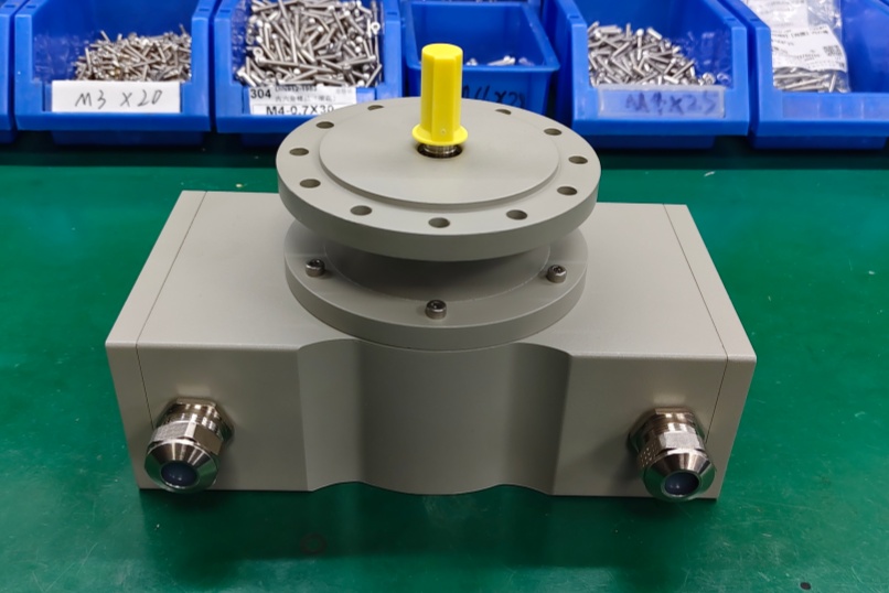
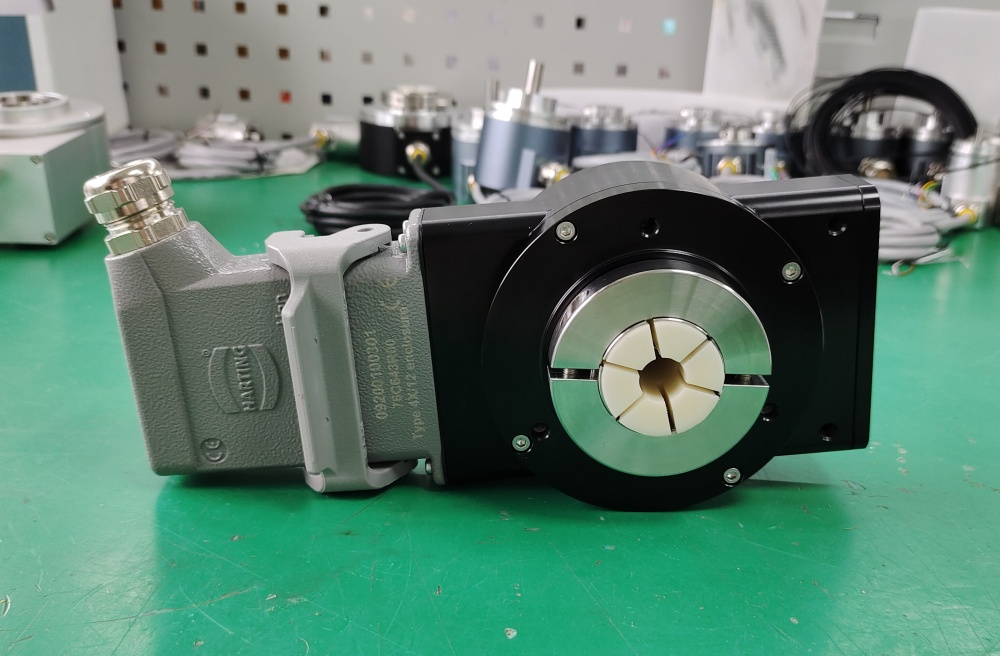
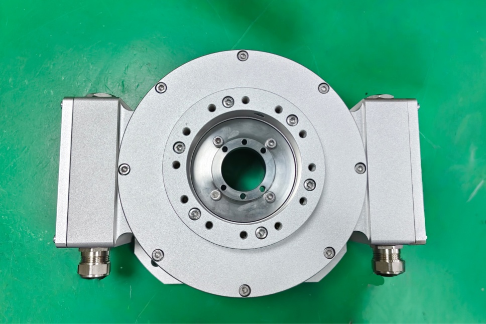
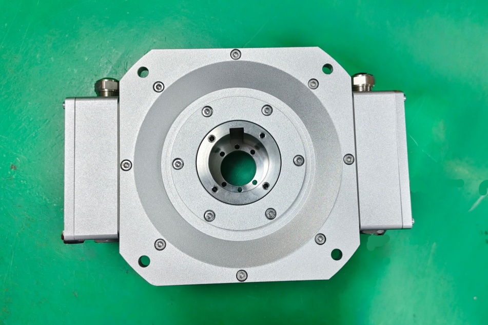
The FGH6KK-2000G-90G-NG-J/50P is a heavy-duty incremental encoder configuration built on the FGH 6 platform. In this type code, KK indicates a version with two terminal boxes, and the catalog also notes that this arrangement is used for versions with Option S when applicable. The 50P shaft code identifies a Ø50 H7 hollow shaft, while 2000G defines the pulse count and 90G / NG indicate a 90° pulse channel with inverted signals and a reference pulse with inverted signal. The FGH(I) 6 platform supports square-wave pulse rates including 2000 and 2048, with supply options of 12–30 VDC and optional 5 VDC versions.
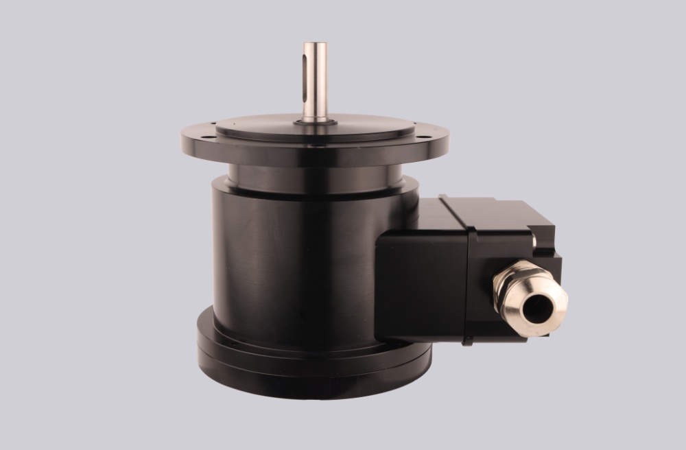
From the series data, FGH(I) 6 encoders are intended for demanding industrial duty with robust hollow-shaft construction, terminal-box connection formats, and high protection capability. The catalog presents FGH 6 as part of an incremental encoder family for heavy industry and harsh conditions, which supports using this model in rotating machinery, drive systems, and general industrial feedback applications where installation continuity is important.
Industrial Integration Considerations
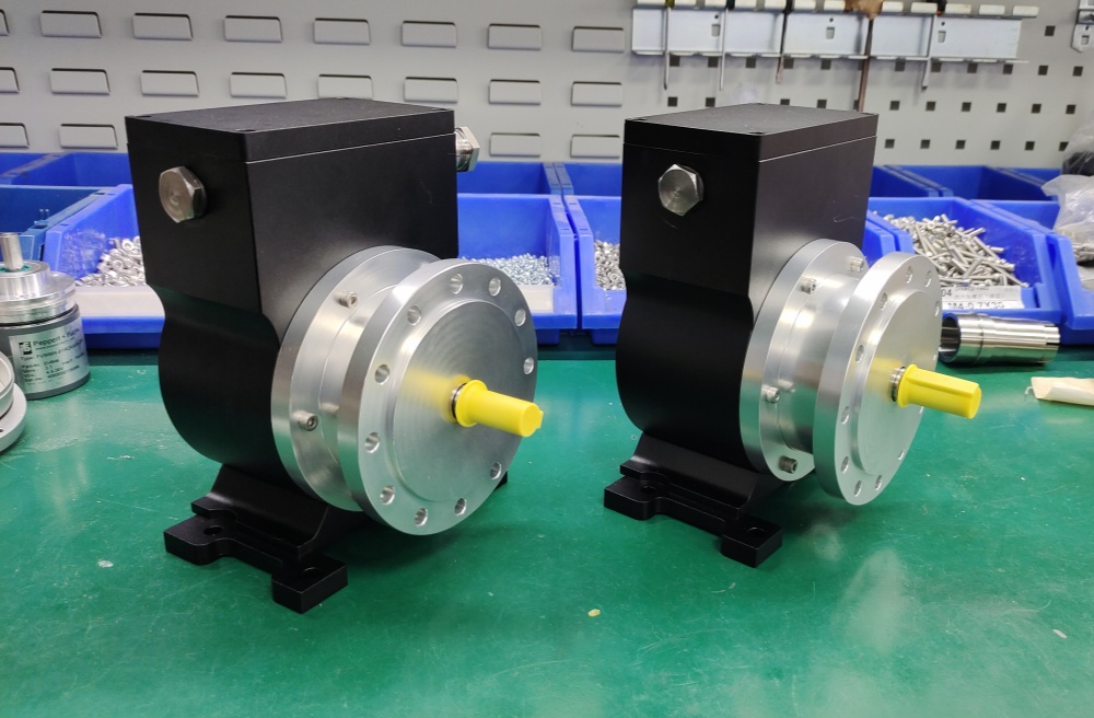
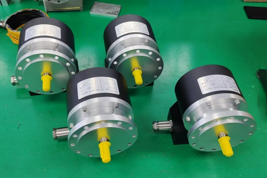
For this model, the primary integration point is the Ø50 hollow shaft interface. During retrofit work, shaft diameter, tolerance fit, anti-rotation support, mounting flange relationship, and available axial installation space should be checked carefully. The FGH 6 dimension drawing for the hollow-shaft design shows this 50 mm bore arrangement together with a large mechanical mounting envelope, which means replacement projects should verify surrounding clearance rather than assuming compact encoder geometry.
The dual terminal-box construction also affects field integration. In practice, cable routing, shielding continuity, grounding quality, and service accessibility should be reviewed before installation. For applications using existing controllers, the 2000 ppr incremental output, 90° pulse track, and reference pulse structure should be checked against the receiving input card to maintain stable signal interpretation during operation.
Custom Compatible Encoder Solution
For the FGH6KK-2000G-90G-NG-J/50P, a custom compatible encoder solution can be engineered to match the original hollow-shaft concept, terminal-box wiring layout, pulse count, and signal arrangement. The compatible solution can be tailored around the Ø50 H7 shaft interface, installation geometry, output logic, and field connection requirements so that changes to the existing machine layout are kept to a minimum.
This model also includes the J option in the type code. The catalog identifies J as an available signal-related option within the FGH(I) 6 coding structure, so it should be confirmed during engineering review and carried over correctly in any compatible design. That helps preserve the original signal behavior and avoids mismatch during commissioning.
Lead Time and Custom Development
Typical production lead time: 30 working days.
Before production, the engineering review should confirm the hollow-shaft diameter, installation envelope, terminal-box arrangement, pulse count, output requirements, controller compatibility, and site conditions. Special attention should be given to the 50 mm shaft fit, cable entry orientation, and the exact meaning of the J-coded configuration in the installed system so the compatible solution can be aligned with the original application logic.
Typical Technical Parameters
| Parameter | Specification |
|---|---|
| Encoder Type | Incremental encoder |
| Resolution | 2000 ppr |
| Output Type | Incremental output |
| Signal Format | 90° pulse channel with inverted signals, reference pulse with inverted signal |
| Supply Voltage | 12–30 V DC, optional 5 V DC |
| Connection Type | Terminal box connection |
| Electrical Arrangement | Two terminal boxes |
| Shaft Type | Hollow shaft |
| Shaft Diameter | Ø50 H7 |
| Mounting Style | Heavy-duty hollow-shaft industrial design |
| Protection Rating | Up to IP66 |
| Operating Temperature | -25 °C to +85 °C |
| Option Code | J option included |
| Application Orientation | Maintenance, retrofit, replacement, upgrade |