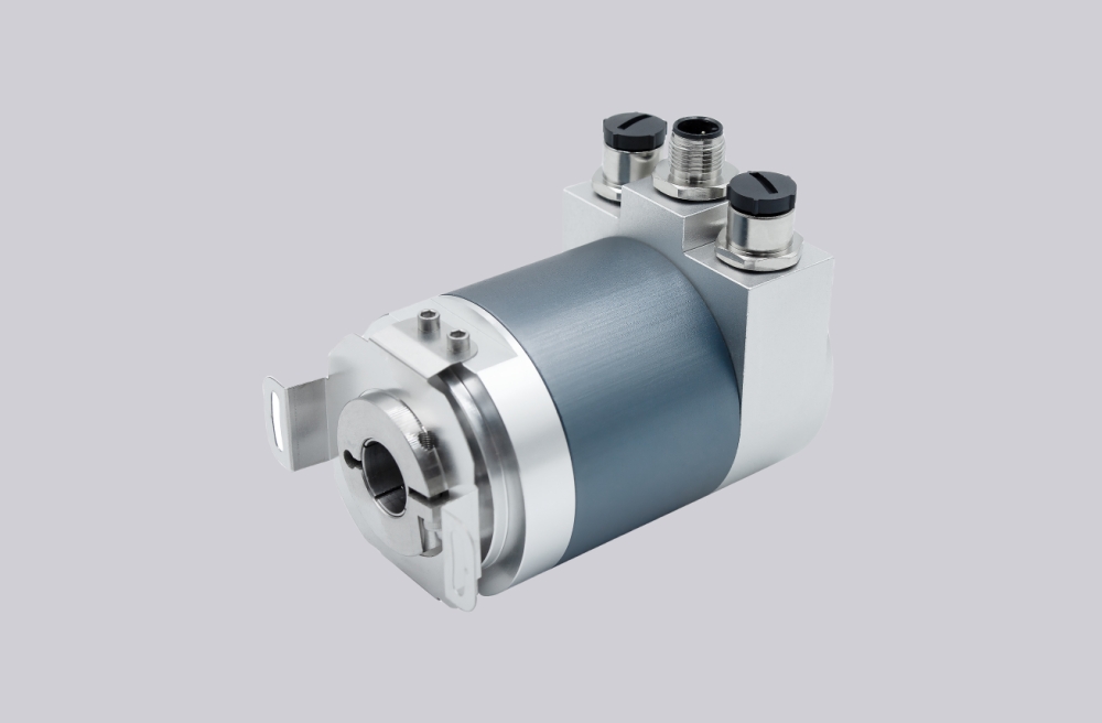
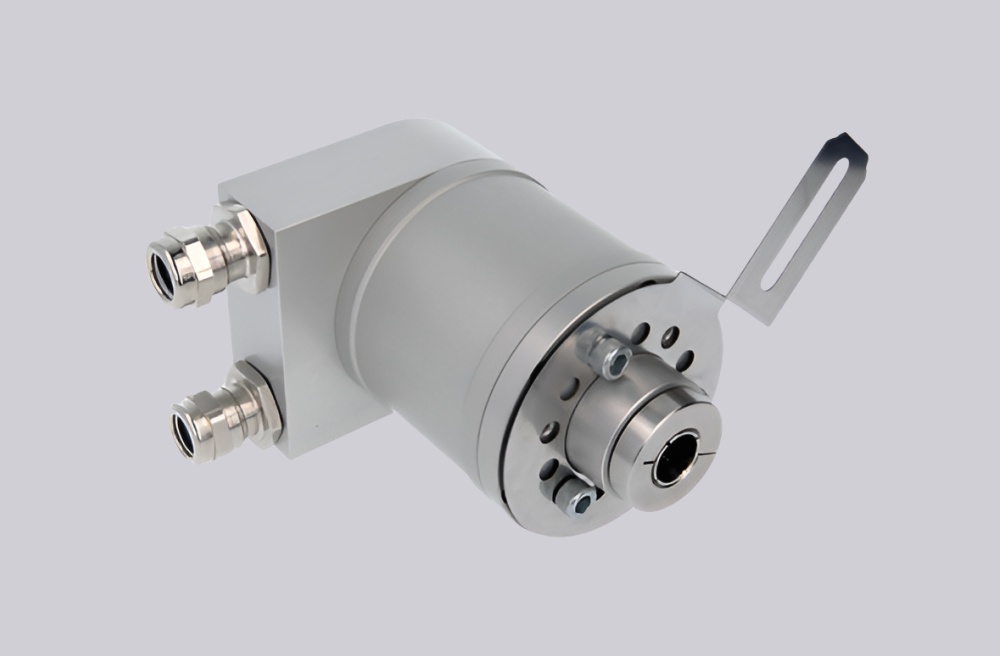
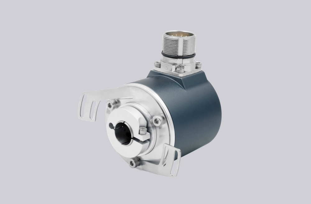
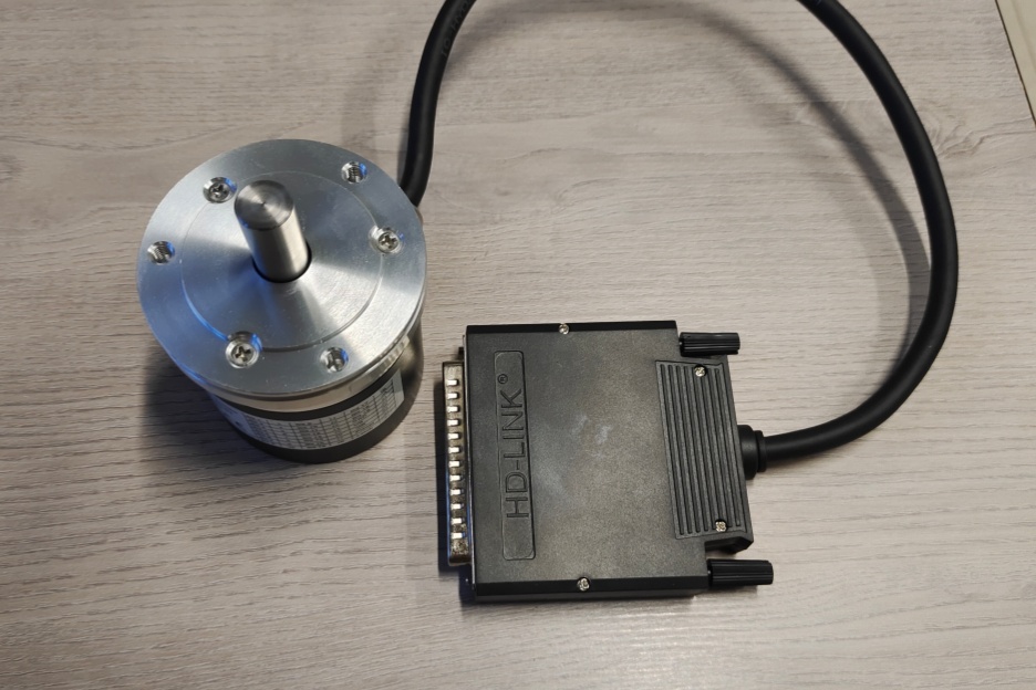
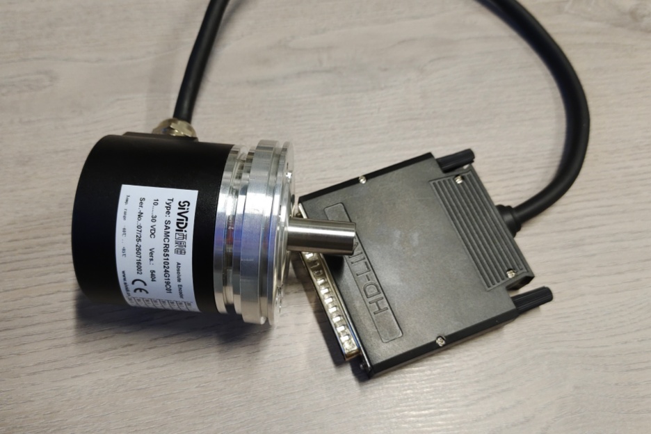
For the CR105-1024R14A03 parallel absolute encoder, we deliver a precision 1:1 custom replacement solution engineered for legacy equipment support. This service is developed for projects where the original encoder is no longer readily available or procurement lead times have become unpredictable. Our engineering team rebuilds the mechanical footprint and electrical architecture according to verified technical data, including flange geometry, shaft dimensions, wiring orientation, and parallel signal format. The replacement unit is manufactured to integrate seamlessly into existing systems, allowing direct installation without structural modifications or PLC reprogramming. Typical production lead time is controlled within 15 working days, supporting urgent maintenance schedules and minimizing operational disruption.
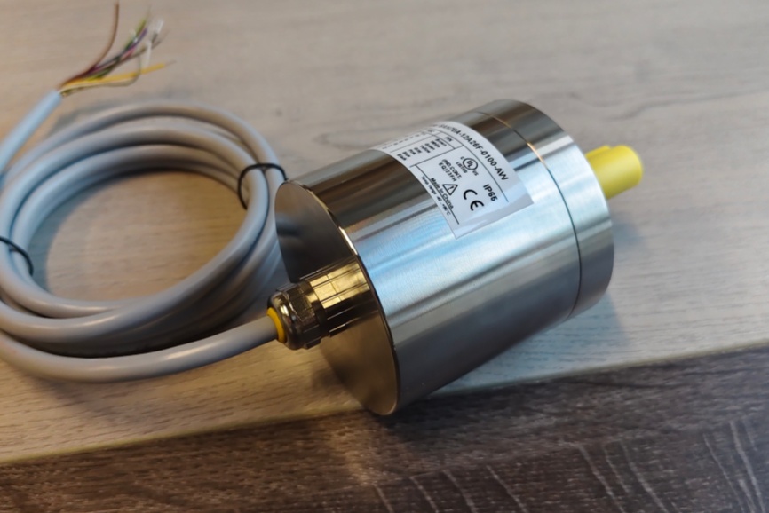
This customized solution has been adopted in demanding automation environments requiring stable multi-bit parallel output and reliable position feedback. It performs consistently under mechanical vibration, continuous duty cycles, and fluctuating load conditions. International users appreciate the balanced combination of structural robustness, signal stability, and optimized procurement cost. Through standardized quality verification procedures and streamlined production management, we ensure repeatable manufacturing accuracy and dependable delivery performance, helping industrial operators maintain equipment lifecycle continuity and reduce unexpected downtime risks.
Technical data
| Parameter | Value |
|---|---|
| Resolution | 2 to 4096 positions / 360° |
| Measuring range | 2 to 4096 turns |
| Total number of positions | |
| Measurement position deviation | |
| Output frequency* | 30 kHz max. up to 10 Bit / 360°; 10 kHz max. from 11 Bit |
| Disc coding | Gray code |
| Output code, parallel | Gray or Natural Binary |
| Code sense, serial | CW or CCW (Signal input E2) |
| Logic polarity | Positive |
| Memory circuit | Store or not store, signal input E1 |
| Enable circuit (for bus operation) | Active or inactive, (signal input E1) |
| Sensor system | GaAlAs diodes, photo-transistor array |
| Parallel output circuits | A = Open collector Darlington; B = Open collector, TTL compatible; C = Open emitter Darlington; D = Push-pull, Totem-pole |
| Serial output SSI | Differential data output to RS 422 |
| Clock input SSI | Differential (opto-coupler) for data driver to RS 422 |
| Supply voltage range | +11 V to +26 VDC |
| Supply current | Parallel: 90 mA typ. / 120 mA max.; Serial GSI: 130mA typ. / 160mA max. |
| Operating speed | 3000 rpm max. (continuous); 4000 rpm max. (short period) |
| Angular acceleration | 10° rad/s² max. |
| Inertial mass of rotor | ≤ 5 Ncm (8 Ncm - CR 66) |
| Wind-up torque | ≤ 1 Nm (4 Ncm - CR 66) |
| Permissible axial and radial shaft load | 250 N max. |
| Bearing life expectancy | 10⁹ revolutions |
| Operating temperature range | -20°C to +60°C |
| Storage temperature range | -25°C to +70°C |
| Permissible rel. humidity | 85% without condensation |
| Resistance to shock | 200 m/s², 11 ms (DIN IEC 68) |
| Resistance to vibration | 5 Hz..1000 Hz; 100 m/s² (DIN IEC 68) |