The FG2AK-1024G-90G-NG encoder can be supported through a custom compatible solution for machine maintenance, retrofit work, and replacement planning. A compatible engineering version can be prepared against the existing installation requirements, and the usual lead time is 10–15 working days.
Technical Overview of the FG2AK-1024G-90G-NG Encoder
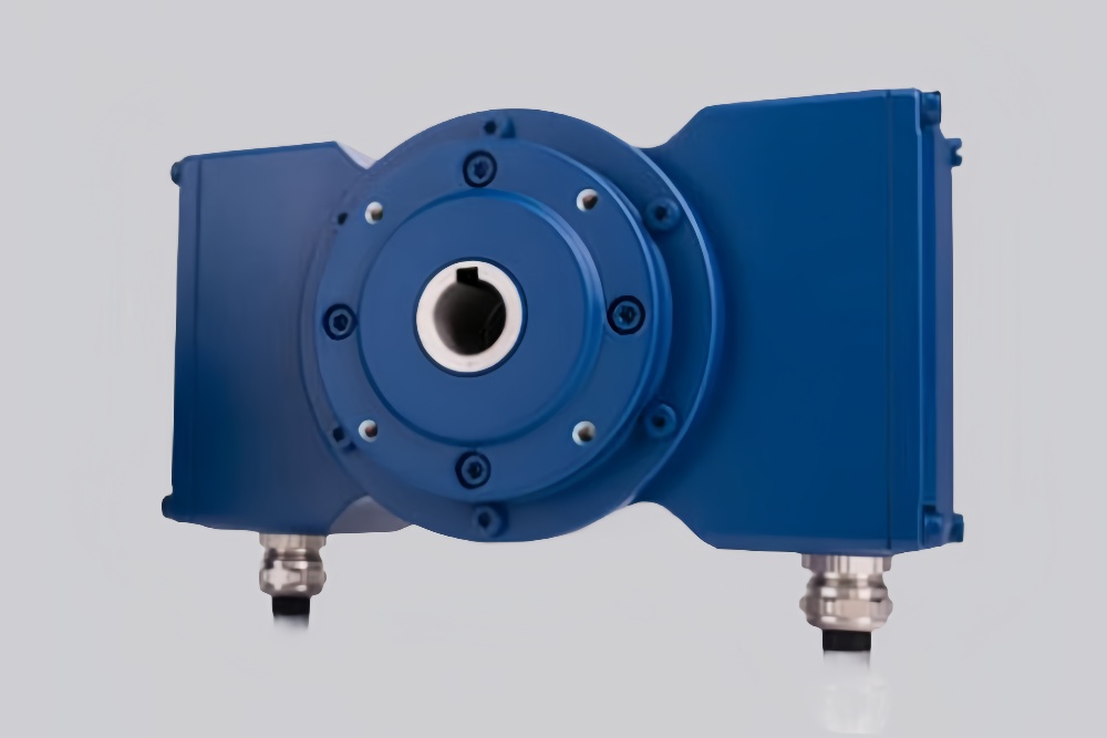
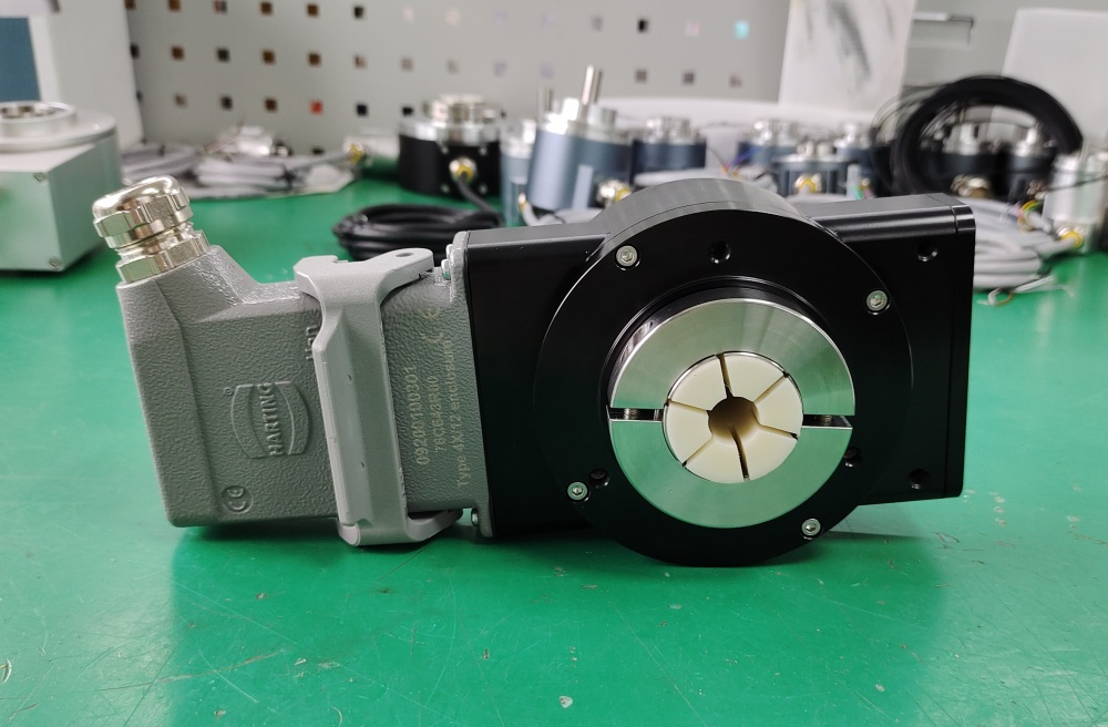
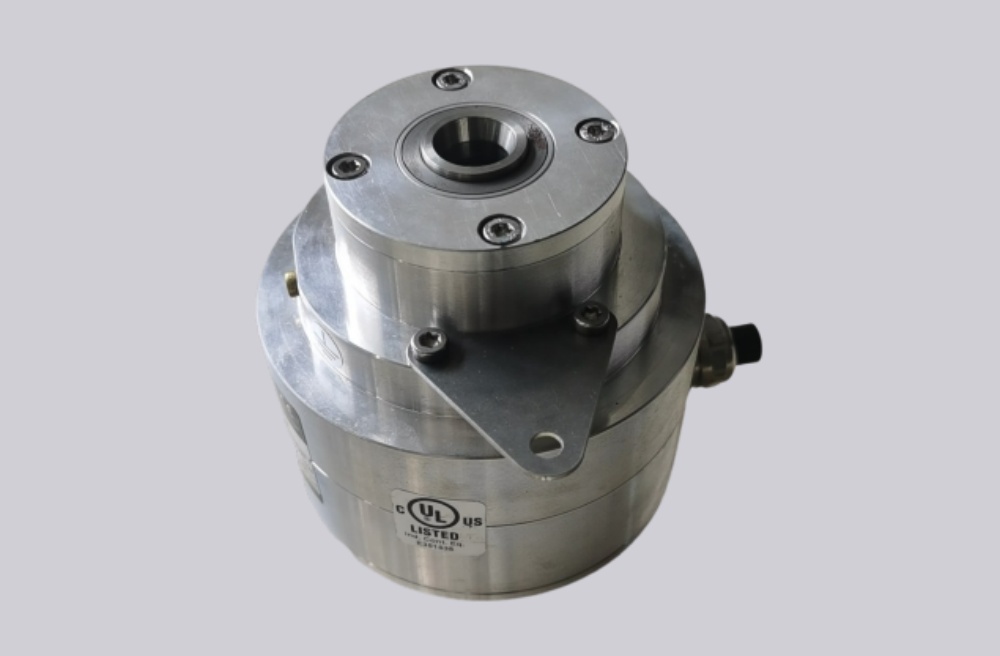
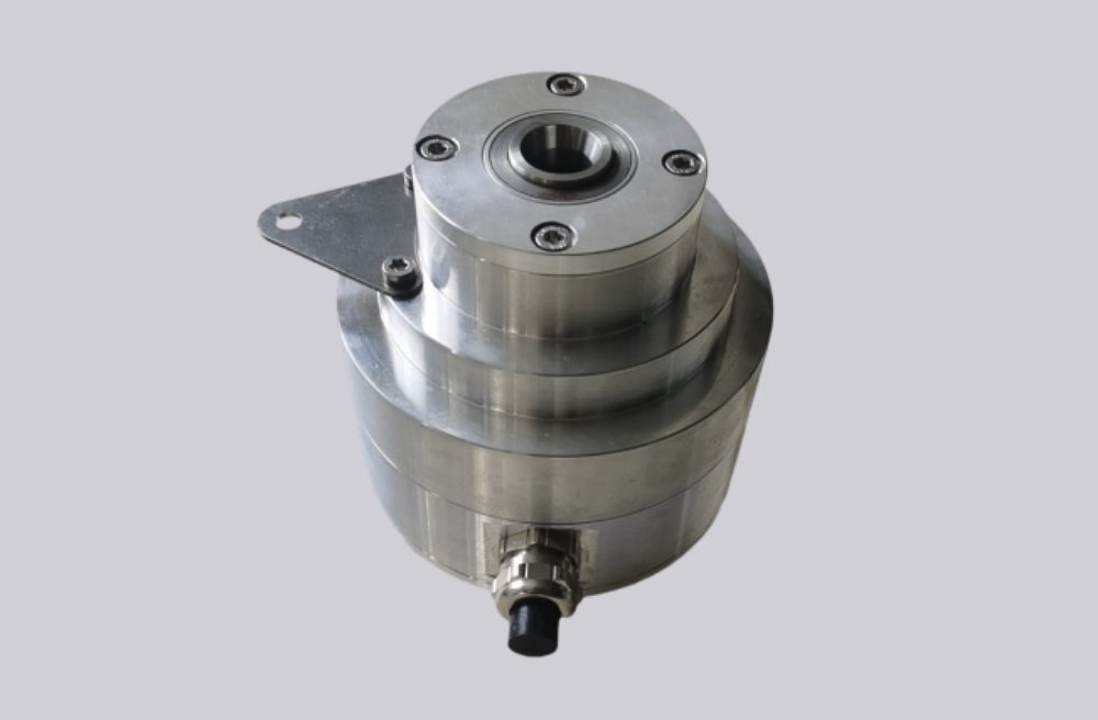
The FG2AK-1024G-90G-NG is an incremental encoder configuration from the solid-shaft side of the series. It uses a 1024 ppr signal structure and, based on the AK configuration code, a single-system arrangement with terminal strip connection. In contrast to the hollow-shaft FGHJ variants, this version is built around a solid shaft design, which changes the main integration focus toward coupling selection and shaft alignment.
Series-level data indicates industrial-duty construction with 12–30 V DC supply, HTL output as the standard signal level, and optional TTL where required. The encoder family also supports IP66 protection and operation in demanding industrial environments where robust mechanical installation and stable electrical feedback are required.
Industrial Integration Considerations
For this solid-shaft model, the main mechanical consideration is the coupling arrangement between the encoder shaft and the driven shaft. Alignment quality, coupling stiffness, radial load transfer, and mounting bracket stability all affect service life and signal quality. In retrofit projects, the shaft extension, flange fit, and available installation depth should be checked before selecting a compatible solution.
On the electrical side, terminal strip connection allows practical field wiring, but shielding and grounding must still be implemented carefully. Existing controller input requirements, pulse evaluation capability, and reference pulse usage should also be reviewed, especially when the machine has legacy control hardware.
Custom Compatible Encoder Solution
For the FG2AK-1024G-90G-NG, a custom compatible encoder solution can be developed to match the original shaft concept, mounting arrangement, connection style, and signal behavior. The compatible version can be aligned around pulse count, output level, cable termination logic, and installation envelope so that the replacement process remains straightforward.
This type of engineering support is useful in cases where the original model is difficult to purchase quickly or where a maintenance project requires a stable, installation-conscious substitute without unnecessary redesign. The goal is to maintain mechanical continuity and control compatibility at the same time.
Lead Time and Custom Development
Typical production lead time: 10–15 working days.
Before production, engineering confirmation should include shaft dimensions, coupling method, encoder mounting concept, pulse count, output expectations, terminal connection details, and environmental conditions. Where space, vibration, or cable routing is critical, these items should be reviewed early in the project.
Typical Technical Parameters
| Parameter | Specification |
|---|---|
| Encoder Type | Incremental encoder |
| Resolution | 1024 ppr |
| Output Type | Incremental output |
| Signal Format | HTL, optional TTL |
| Supply Voltage | 12–30 V DC |
| Interface | Terminal strip connection |
| Shaft Type | Solid shaft |
| Shaft Diameter | Series solid shaft design |
| Protection Rating | IP66 |
| Operating Temperature | -25 °C to +85 °C |
| Max Speed | Up to 7000 rpm |
| Mechanical Structure | Solid shaft industrial design |
| Application Orientation | Maintenance, retrofit, replacement, upgrade |