The FGH40KK-1024G-90G-NG/20P can be supported through a custom compatible encoder solution for retrofit execution, maintenance replacement, equipment servicing, and upgrade work. Where the installed system depends on a hollow-shaft feedback arrangement with established controller-side logic, a project-matched compatible version can be developed with a standard production lead time of 30 working days.
Technical Overview of the FGH40KK-1024G-90G-NG/20P Encoder
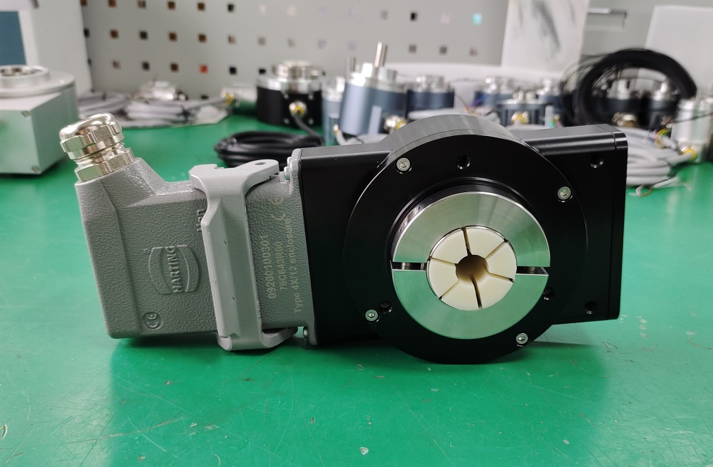
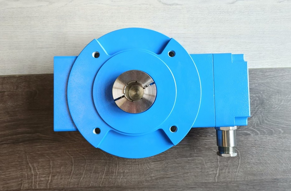
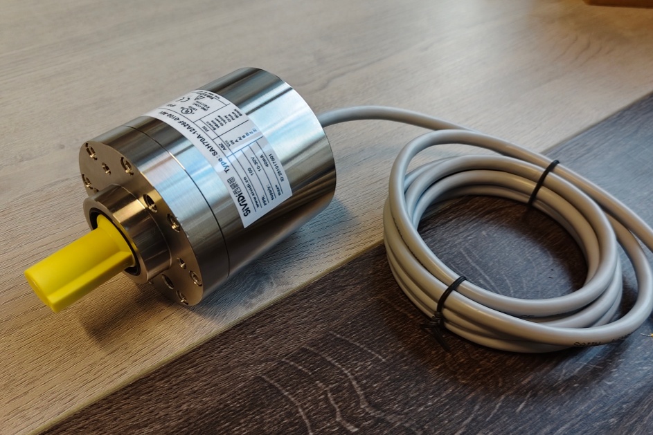
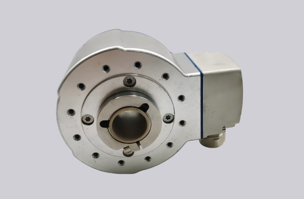
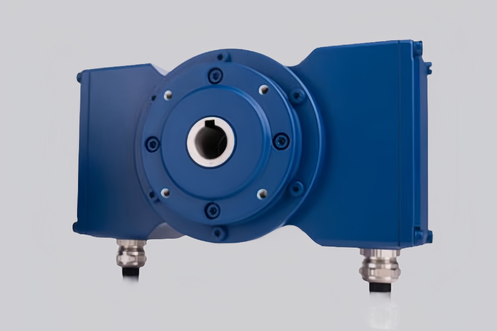
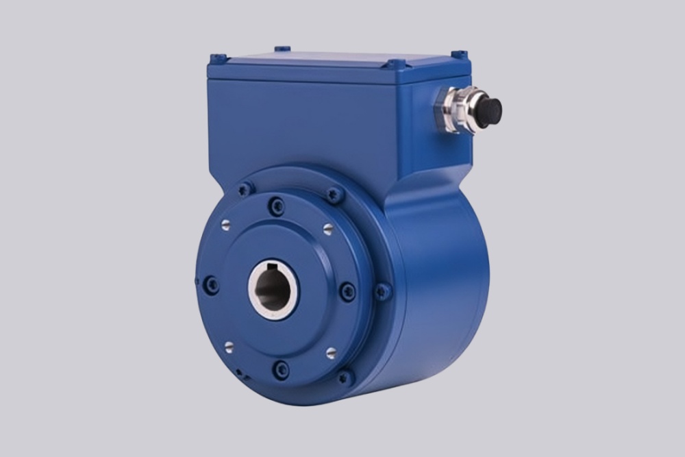
The FGH40KK-1024G-90G-NG/20P is an incremental hollow shaft encoder intended for rotary motion measurement in industrial feedback systems. The latest FGH 40 user manual identifies this family as an Incremental Hollow Shaft Encoder, and the square-wave output table explicitly includes 1024 among the standard pulse values. In this model code, 1024G defines a 1024 ppr output structure, while 90G / NG indicates the incremental signal arrangement with quadrature-style phase displacement and reference pulse logic. The same manual confirms 12–30 V DC supply, HTL as the standard output level, optional 5 V TTL / RS422-compatible output, and a maximum output frequency of 200 kHz.
Within the FGH 40 family, the 1024 ppr version is especially relevant for retrofit projects because it aligns well with many existing controller and counter configurations that were originally built around conventional incremental resolutions. The manual also specifies square-wave signal characteristics of 0° / 90° channels, 1:1 ±3% duty cycle, and 90° ±3% phase displacement. In addition, it distinguishes between one terminal box and two terminal boxes (redundant version), so the KK configuration remains a meaningful installation feature rather than just a code suffix.
Industrial Integration Considerations
For this model, the most important integration advantage is often controller compatibility. In many existing machines, 1024 ppr is a practical resolution because it can be processed reliably by legacy speed monitors, counters, and PLC-related input structures without pushing signal density too high. During replacement work, pulse acceptance, input voltage range, shielding quality, and reference pulse interpretation should still be checked carefully so that the compatible encoder can be matched to the installed control environment.
The FGH 40 manual also provides clear installation guidance that should be carried into retrofit planning. Proper machine grounding, suitable spacing from inverters, motors, brakes, and contactors, correct shield connection, and suppression of inductive loads are all relevant to long-term signal stability. The manual additionally warns against shock loading and mechanical binding during installation because these conditions can damage the bearing system. In practical terms, this means that electrical compatibility and installation discipline are just as important as matching the shaft and pulse count.
Custom Compatible Encoder Solution
For the FGH40KK-1024G-90G-NG/20P, a custom compatible encoder solution can be engineered to match the original machine interface as closely as possible. The compatible version can be configured around the required hollow-shaft arrangement, 1024 ppr output, output level, signal format, terminal-box concept, and field installation logic so that machine modification is minimized during maintenance or retrofit work.
This is particularly useful where the original equipment relies on an established 1024-based feedback structure and where replacement must be completed without changing the existing controller architecture. By preserving electrical behavior, shaft-side compatibility, and installation continuity together, the compatible solution helps reduce commissioning uncertainty and supports more efficient service work.
Lead Time and Custom Development
Typical production lead time: 30 working days.
Before production, the engineering review should confirm the pulse count, supply voltage, output type, signal format, shaft arrangement, terminal-box layout, controller input expectations, and field installation conditions. Sealing and protection requirements should also be verified in advance, because the latest manual states that the FGH 40 family supports IP65 / IP66 depending on configuration, and that sealing conditions influence permissible speed and breakaway torque.
Typical Technical Parameters
| Parameter | Specification |
|---|---|
| Encoder Type | Incremental hollow shaft encoder |
| Resolution | 1024 ppr |
| Output Type | Square-wave incremental output |
| Signal Format | 0° / 90° channels with reference pulse |
| Supply Voltage | 12–30 V DC |
| Output Level | HTL, optional 5 V TTL / RS422-compatible |
| Max Frequency | 200 kHz |
| Duty Cycle | 1:1 ±3% |
| Phase Displacement | 90° ±3% |
| Connection Type | Terminal box configuration |
| Terminal Box Arrangement | KK version |
| Shaft Type | Hollow shaft |
| Shaft Code | /20P |
| Protection Rating | IP65 / IP66 depending on configuration |
| Application Orientation | Maintenance, retrofit, replacement, upgrade |