A custom compatible encoder solution can be provided for 8.9080.3531.3001 in projects where the original large-bore encoder arrangement must be maintained with minimal installation disturbance. This version uses a 28 mm through hollow shaft, long spring element mounting, and cable gland terminal cover on a multiturn PROFIBUS DP absolute encoder platform. Typical production lead time: 15 working days. The central engineering issue for this model is preserving the combination of large shaft passage and spring-supported housing restraint.
Technical Overview of the 8.9080.3531.3001 Encoder
The 8.9080.3531.3001 shares the general 9080 platform characteristics: PROFIBUS DP interface, RS485 communication layer, binary code structure, 10 ... 30 V DC supply, and scalable multiturn resolution up to 25 bits total. It supports parameter programming for direction, scaling, preset, and diagnostics mode, which is important in systems where the encoder is part of a commissioned bus environment rather than a simple standalone sensor.
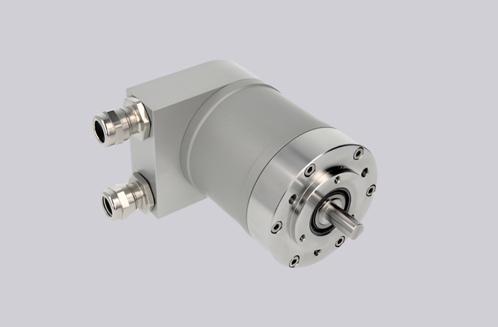
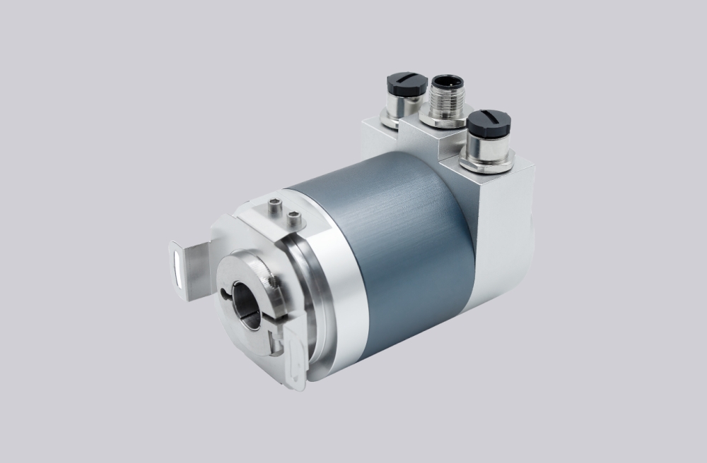
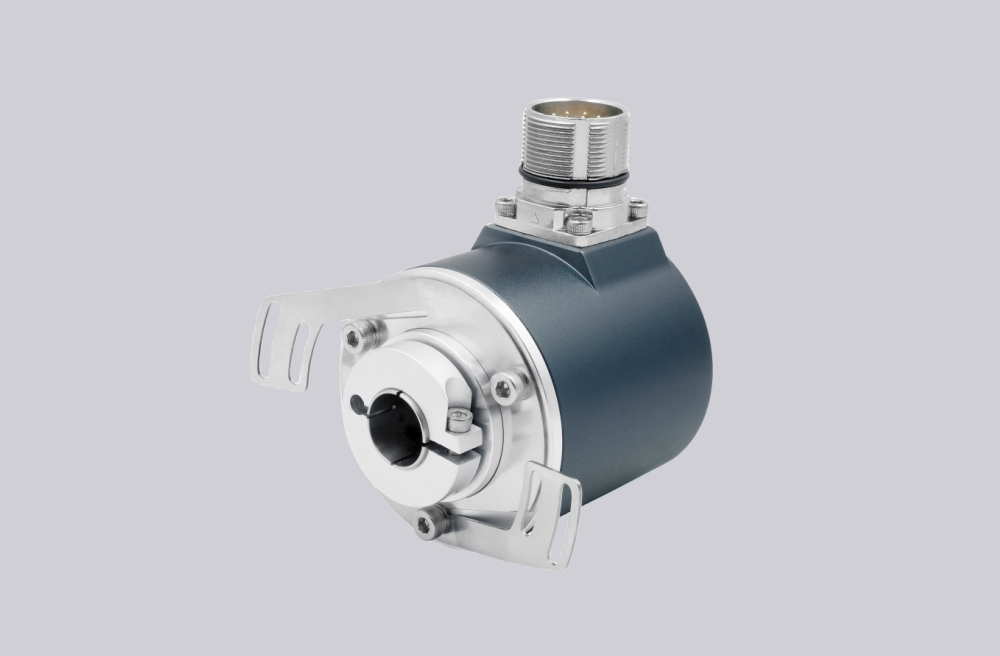
Its distinguishing coded features are flange type 3, shaft code 5, and connection type 1. That means long spring element, 28 mm H7 through hollow shaft, and cable gland M16 terminal box. This makes it one of the larger bore versions in the series and therefore more sensitive to shaft-side dimensional continuity.
Industrial Integration Considerations
A 28 mm hollow shaft version is typically selected because the machine drive side demands that bore size; it is not usually a trivial variation. For maintenance support and retrofit work, shaft diameter, clamping condition, and housing restraint all deserve close review. If the original installation used a long spring element to absorb mounting tolerance while stabilizing housing rotation, that concept should remain intact in the replacement plan.
The cable gland style may also be deliberate in environments where sealed direct cable entry is preferred over plug connections. Keeping the same field connection logic often simplifies replacement work and supports the existing EMC and grounding practice already implemented on site.
Custom Compatible Encoder Solution
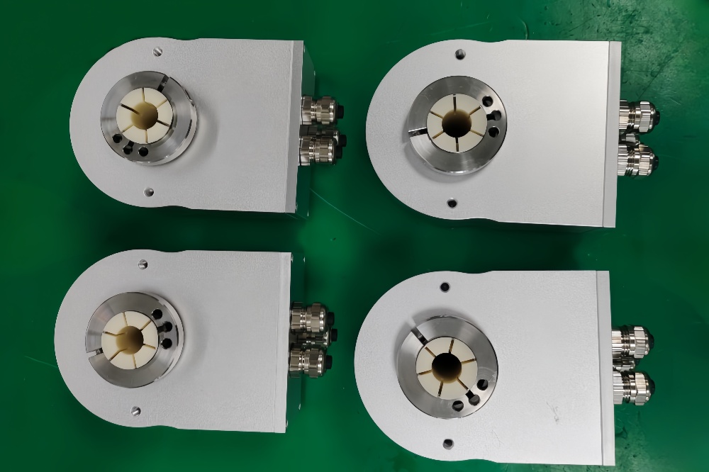
For 8.9080.3531.3001, engineering compatibility depends on matching the large through-bore geometry as closely as the electrical interface. A custom compatible encoder solution should therefore be designed around the 28 mm shaft, long spring element, cable gland terminal cover, and PROFIBUS DP class 2 integration requirements. This preserves the installation logic that originally justified the use of this configuration.
Where the controller uses scaled total resolution or programmed preset behavior, those items should also be reviewed during configuration matching so the replacement behaves consistently after commissioning.
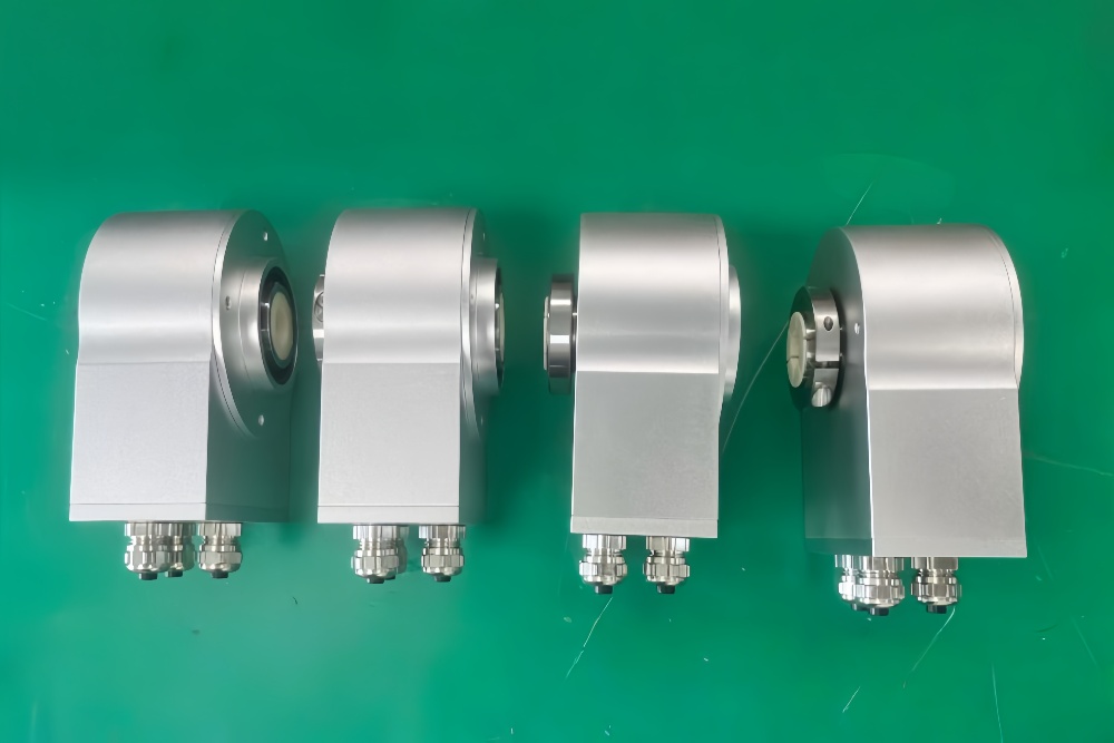
Custom Solution Photos
Lead Time and Custom Development
Typical production lead time: 15 working days.
Custom development should verify shaft size, spring element mounting position, cable entry method, and bus configuration parameters. On this model, shaft-side compatibility is usually the first engineering checkpoint because the 28 mm bore is a defining installation feature.
Typical Technical Parameters
| Parameter | Specification |
|---|---|
| Encoder Type | Multiturn absolute encoder |
| Model | 8.9080.3531.3001 |
| Interface | PROFIBUS DP |
| Protocol Profile | Class 2 |
| Physical Layer | RS485 |
| Supply Voltage | 10 ... 30 V DC |
| Resolution Singleturn | 1 ... 8192, scalable |
| Multiturn Capability | 1 ... 4096, scalable |
| Max Overall Resolution | 25 bit |
| Code Type | Binary |
| Shaft Type | Through hollow shaft |
| Bore Size | 28 mm H7 |
| Mounting Style | Spring element, long |
| Connection Type | Removable bus terminal cover with cable gland M16 |
| Protection Rating | IP65 |
| Operating Temperature | -10°C ... +70°C |
| Max. Speed | 6000 min⁻¹ max., 3000 min⁻¹ continuous |