A project-specific compatible encoder solution can be arranged for 8.9080.3132.3001 when the goal is to preserve machine-side PROFIBUS integration while updating or replacing the encoder hardware. This model combines a long spring element fixing method with a 12 mm through hollow shaft and 3 x M12 connector layout. Typical production lead time: 15 working days. It is well suited to applications where connectorized field wiring and flexible anti-rotation mounting both need to be retained.
Technical Overview of the 8.9080.3132.3001 Encoder
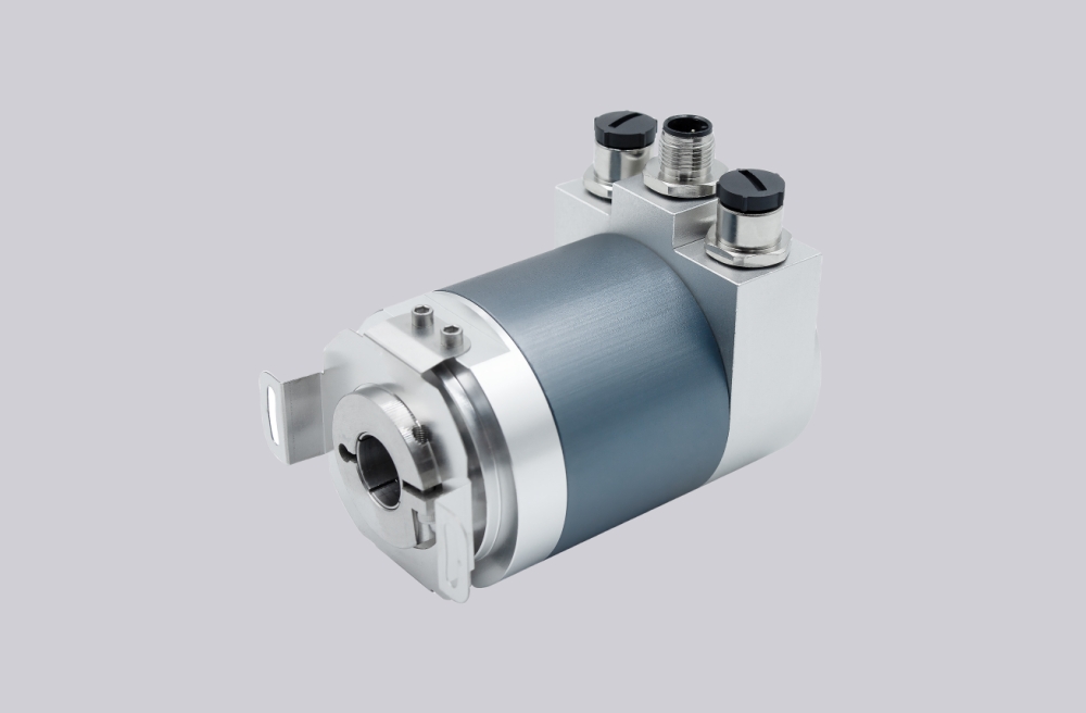
The 8.9080.3132.3001 is based on a multiturn absolute encoder platform with PROFIBUS DP communication, RS485 hardware layer, binary code output, and a scalable maximum resolution of 25 bits. The family allows programming of rotation direction, preset value, and scaling factors, making it adaptable in systems where the controller expects configured rather than fixed position behavior.
Its order code points to flange type 3, shaft code 1, and connection type 2. This means a long spring element version with a 12 mm H7 through hollow shaft and three M12 connectors. That combination can be especially useful in installations where the cable paths are already standardized around circular connectors and where a longer spring element is preferred for mounting geometry reasons.
Industrial Integration Considerations
A long spring element changes the mechanical character of the installation compared with a short spring or rigid flange design. It can offer additional mounting reach and may better suit equipment where the anti-rotation point is positioned farther from the encoder body. For field replacement, the spring element length and fixing location should be preserved to avoid housing stress or unstable restraint during operation.
The M12 connection layout also supports service-friendly wiring, but only when the existing machine uses the same connector logic. Since the datasheet differentiates between terminal-box and M12 styles, the connection version should always be matched to the installed field wiring architecture rather than changed casually during replacement.
Custom Compatible Encoder Solution
For 8.9080.3132.3001, a custom compatible encoder solution should maintain the 12 mm through hollow shaft, long spring element concept, and 3 x M12 connector arrangement together with the original PROFIBUS DP class 2 communication structure. This combination is often chosen where both mounting flexibility and structured fieldbus cabling matter, so preserving both sides of the design is essential for engineering compatibility.
During engineering review, the final coded configuration should also be aligned with the original preset, scaling, and addressing practice already used in the field. That helps ensure installation continuity and avoids unexpected controller-side adjustment work after replacement.
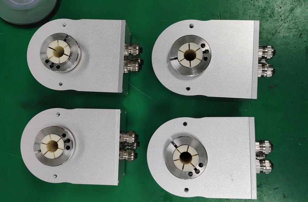
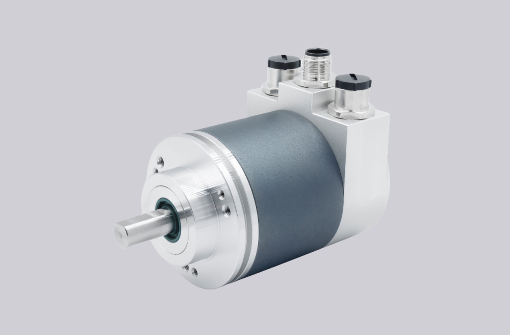
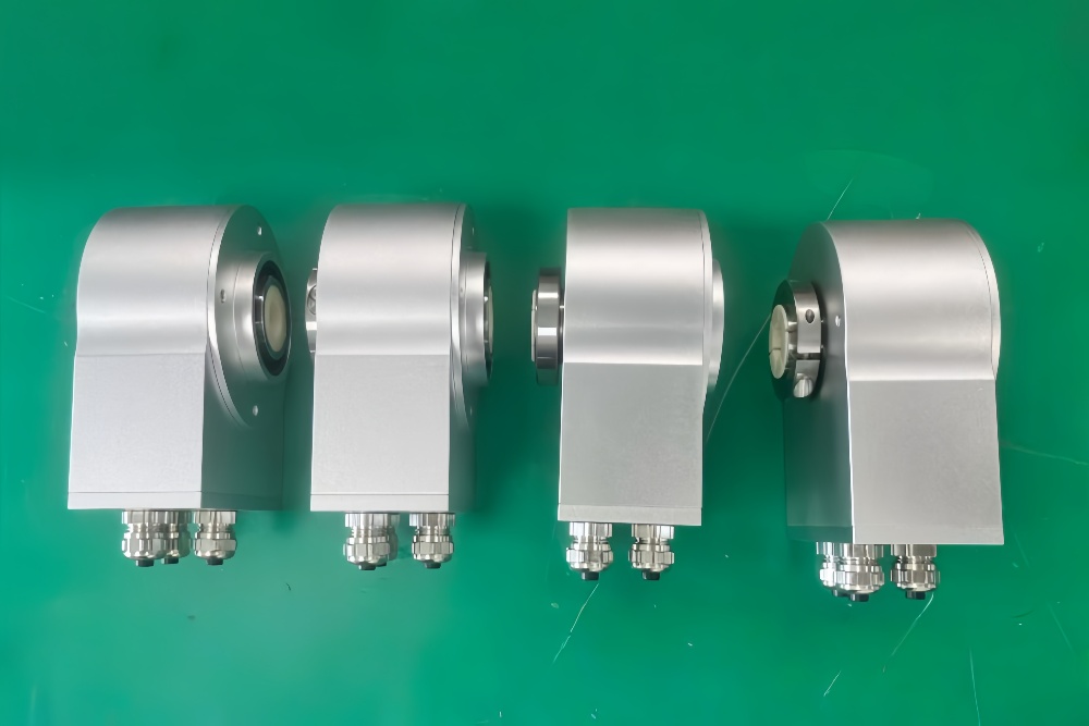
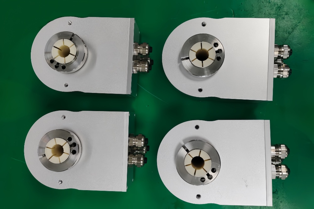
Custom Solution Photos
Lead Time and Custom Development
Typical production lead time: 15 working days.
Development review for this model should confirm spring element geometry, bore fit, connector clearance, and fieldbus topology. Where connector access is limited, plug orientation and cable bend space should also be considered before finalizing the compatible solution.
Typical Technical Parameters
| Parameter | Specification |
|---|---|
| Encoder Type | Multiturn absolute encoder |
| Model | 8.9080.3132.3001 |
| Interface | PROFIBUS DP |
| Protocol Profile | Class 2 |
| Physical Layer | RS485 |
| Supply Voltage | 10 ... 30 V DC |
| Resolution Singleturn | 1 ... 8192, scalable |
| Multiturn Capability | 1 ... 4096, scalable |
| Max Overall Resolution | 25 bit |
| Code Type | Binary |
| Shaft Type | Through hollow shaft |
| Bore Size | 12 mm H7 |
| Mounting Style | Spring element, long |
| Connection Type | 3 x M12 connector |
| Protection Rating | IP65 |
| Operating Temperature | -10°C ... +70°C |
| Max. Speed | 6000 min⁻¹ max., 3000 min⁻¹ continuous |