A custom compatible encoder solution can be provided for FG40K-4096G-90G-NG in maintenance, retrofit, replacement, and upgrade projects. This model is an incremental encoder with radial terminal box connection, 4096 pulses per revolution, and a reference pulse with inverted signal. Typical production lead time: 15 working days. The engineering objective is to preserve the original pulse count, signal output behavior, terminal-box wiring logic, and shaft-side installation continuity so that field replacement can remain practical and stable.
Technical Overview of the FG40K-4096G-90G-NG Encoder
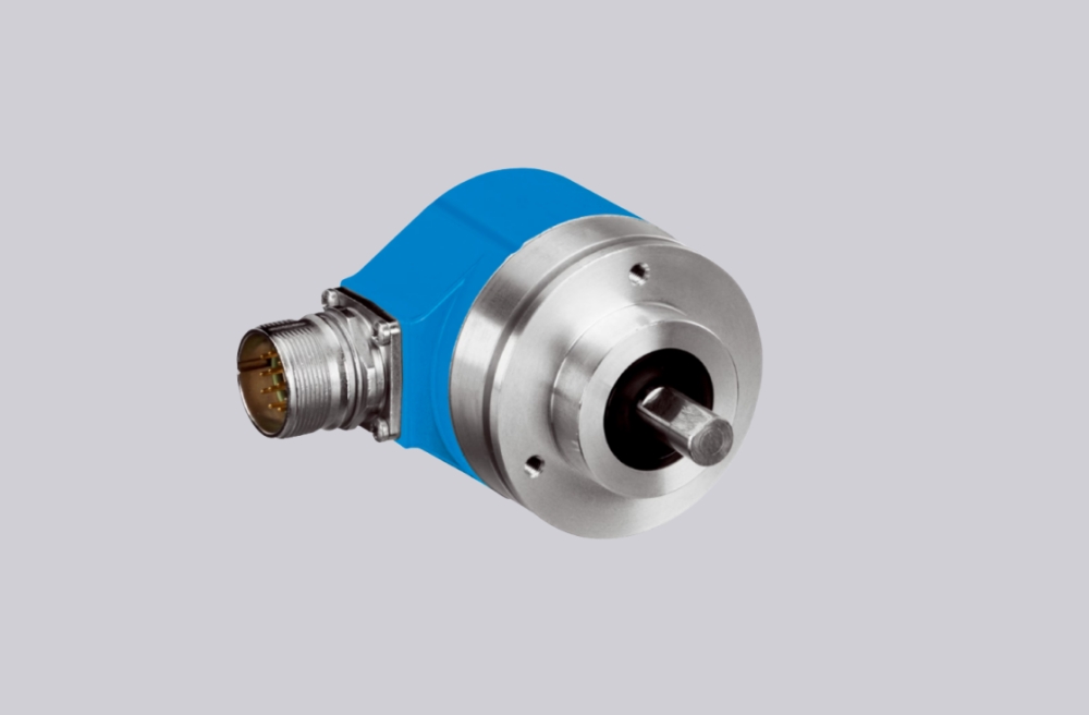
The FG40K-4096G-90G-NG belongs to the FG40 square-wave incremental encoder platform. This coded version uses radial terminal box connection, 4096 pulses per revolution, and the NG option for a reference pulse with inverted signal. The electrical stage is a push-pull line driver with short-circuit protection and integrated impedance adaptation for line resistances from 30 to 140 Ω, which makes it suitable for industrial pulse transmission where stable output behavior and reliable field wiring are required.
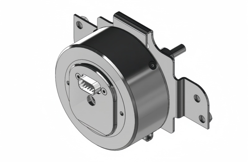
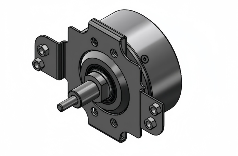
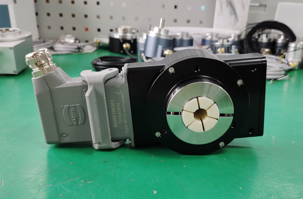
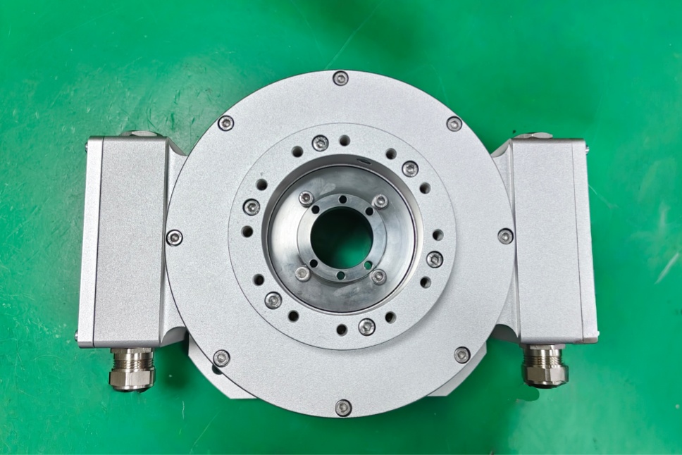
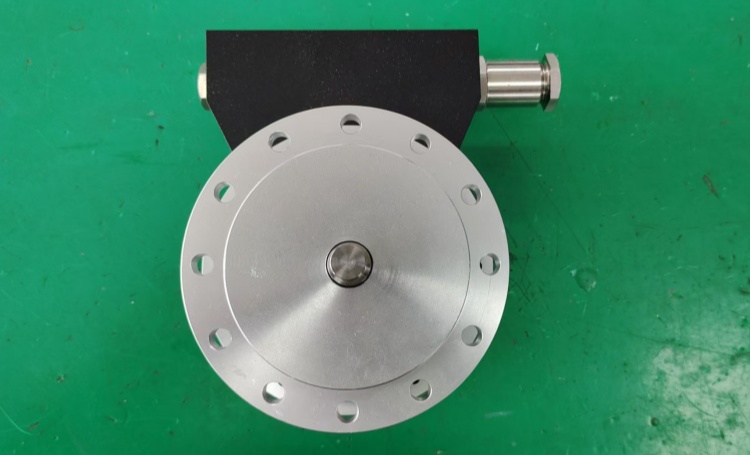
Mechanically, this encoder is built on the FG40 solid-shaft platform with standard shaft dimension 11j6 x 30 mm. The terminal-box layout supports serviceable installation in machinery where cable termination, EMC handling, and maintenance access need to remain straightforward during retrofit or replacement work.
Industrial Integration Considerations
For this model, the 4096 ppr structure is the main control-side compatibility factor. In many applications, this pulse density is selected to provide finer motion feedback than 1024 or 2048 ppr versions while still remaining within practical controller counting limits. During replacement, preserving 4096 pulses per revolution helps keep the original scaling, speed calculation logic, and counter behavior unchanged.
The NG reference pulse option is also important where the machine relies on a defined index position for homing, synchronization, or counter reset. In such cases, replacement planning should preserve not only the main A/B pulse structure, but also the original reference-pulse logic and signal relationship.
From the mechanical side, shaft alignment and coupling condition should be reviewed carefully. The encoder should remain matched to the installed coupling arrangement so that radial force, bearing load, and long-term signal stability remain within the expected range.
Field Installation and Wiring Notes
For radial terminal-box versions, field wiring should remain aligned with the original EMC layout. Encoder cables should be routed away from motors, inverters, contactors, solenoids, and brake wiring. Shield bonding should be maintained on both sides, and the grounding strap should remain short and properly dimensioned so interference immunity remains stable in the installed machine.
The coupling must be mounted without force. Hammering during installation is not permitted, and misalignment should be avoided because it can increase radial load, shorten bearing life, and reduce signal quality. If the original installation uses a zero-backlash torsion-resistant coupling, that arrangement should be preserved during engineering review.
Terminal-box sealing and cable-gland contact should also remain consistent with the original installation, especially in dusty, humid, or vibration-prone environments.
Custom Compatible Encoder Solution
A custom compatible encoder solution for FG40K-4096G-90G-NG should preserve five engineering points: 4096 ppr pulse continuity, radial terminal box connection, NG reference pulse with inverted signal, push-pull line-driver behavior, and solid-shaft mechanical fit. This combination matters because successful field replacement depends on both controller-side signal compatibility and long-term installation stability.
From the electrical side, the compatible solution should remain aligned with the original supply range, output frequency requirements, and reference pulse logic. From the mechanical side, it should preserve shaft dimension, coupling installation conditions, and terminal-box cable-entry practice. Where the original machine depends on index-based homing or synchronized pulse evaluation, those requirements should be confirmed during engineering review before final release.
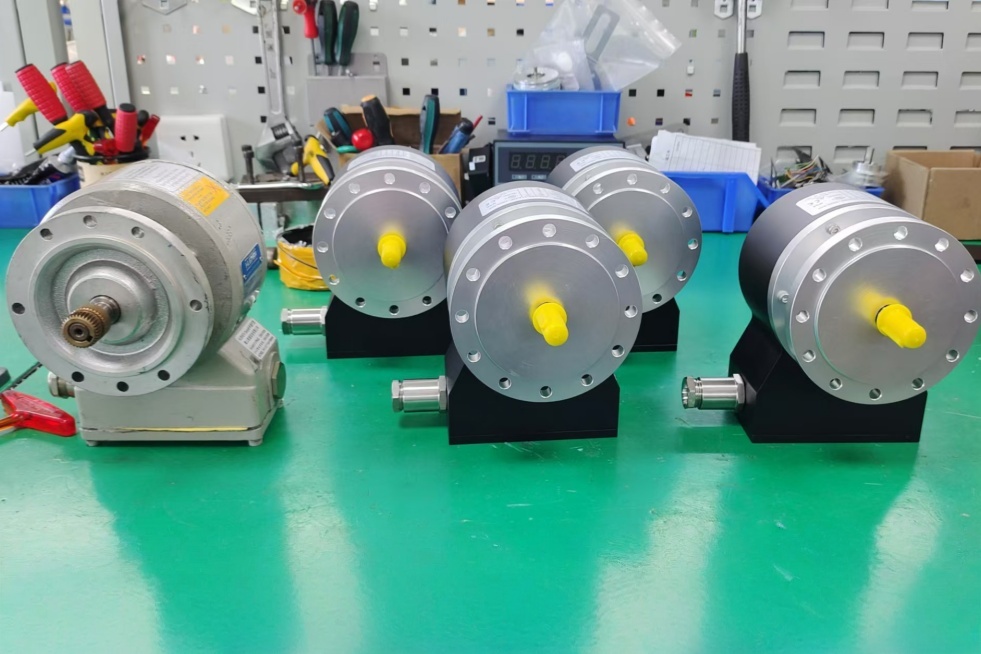
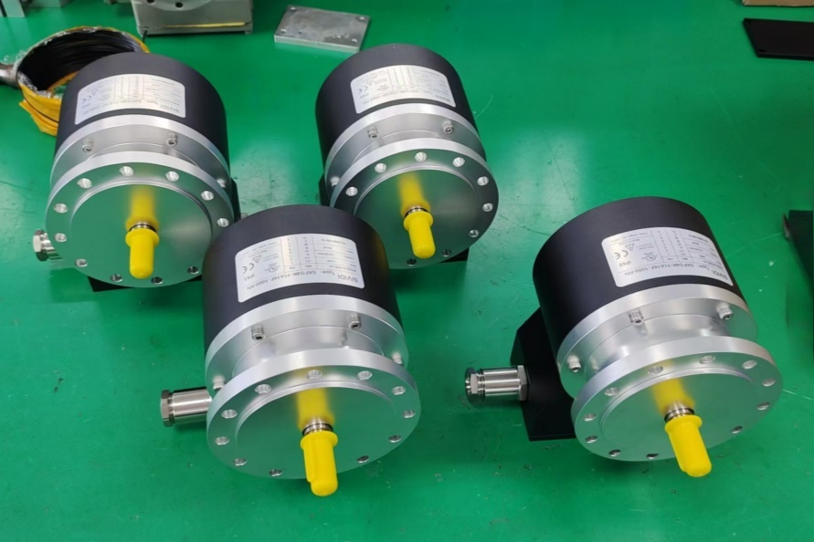
Custom Solution Photos
Lead Time and Custom Development
Typical production lead time: 15 working days.
For custom development, the main checkpoints should include shaft diameter, shaft length, coupling type, radial terminal-box orientation, pulse count continuity, reference pulse requirement, and controller-side frequency margin. EMC cable routing, shield bonding method, and grounding continuity should also be checked so the final solution remains aligned with the installed field configuration.
Typical Technical Parameters
| Parameter | Specification |
|---|---|
| Encoder Type | Incremental encoder |
| Model | FG40K-4096G-90G-NG |
| Output Type | Square-wave pulse output |
| Resolution | 4096 ppr |
| Output Stage | Push-pull line driver |
| Reference Signal | Reference pulse with inverted signal |
| Supply Voltage | 12 ... 30 V DC |
| No-Load Current | Approx. 50 mA at 24 V |
| Max. Output Current | 150 mA at 24 V |
| Max. Output Frequency | 200 kHz |
| Shaft Type | Solid shaft |
| Shaft Dimension | 11j6 x 30 mm |
| Connection Type | Terminal box |
| Exit Position | Radial |
| Protection Rating | IP65 |
| Operating Temperature | 0 ... +70 °C standard |
| Shock Resistance | 150 g |
| Vibration Resistance | 20 g |
| Max. Shaft Load | 100 N axial / 120 N radial |
| Max. Speed | Up to 6000 min⁻¹ depending on sealing |