A tailored compatible encoder solution can be developed for the FGH6KK-2000G-90G-NG-S-J/50P when the project involves maintenance support, retrofit work, replacement planning, or control-system upgrades. For installations that need to retain the original Ø50 hollow-shaft arrangement together with speed-monitoring functionality, the compatible version can be engineered around the existing machine layout, and the standard production lead time is 30 working days.
Technical Overview of the FGH6KK-2000G-90G-NG-S-J/50P Encoder
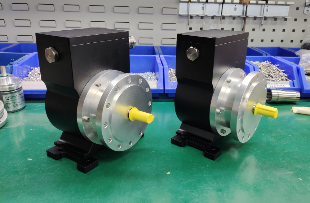
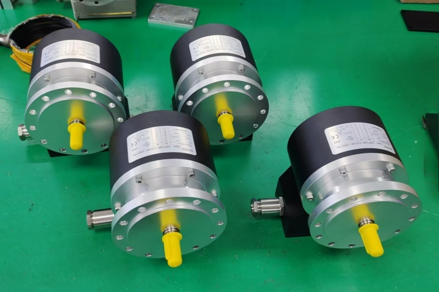
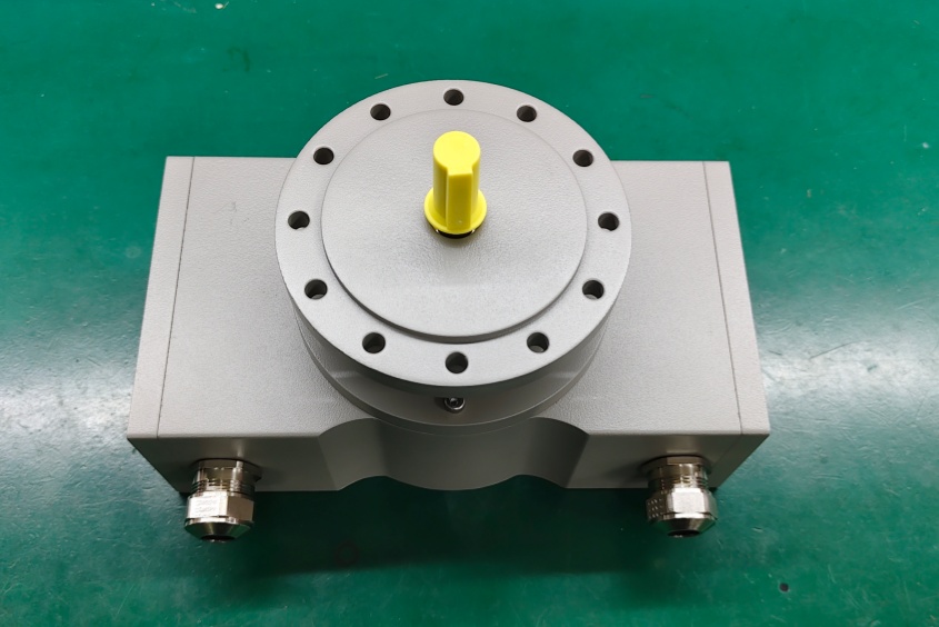
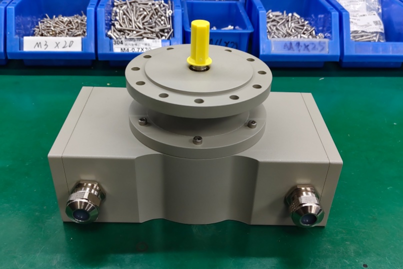
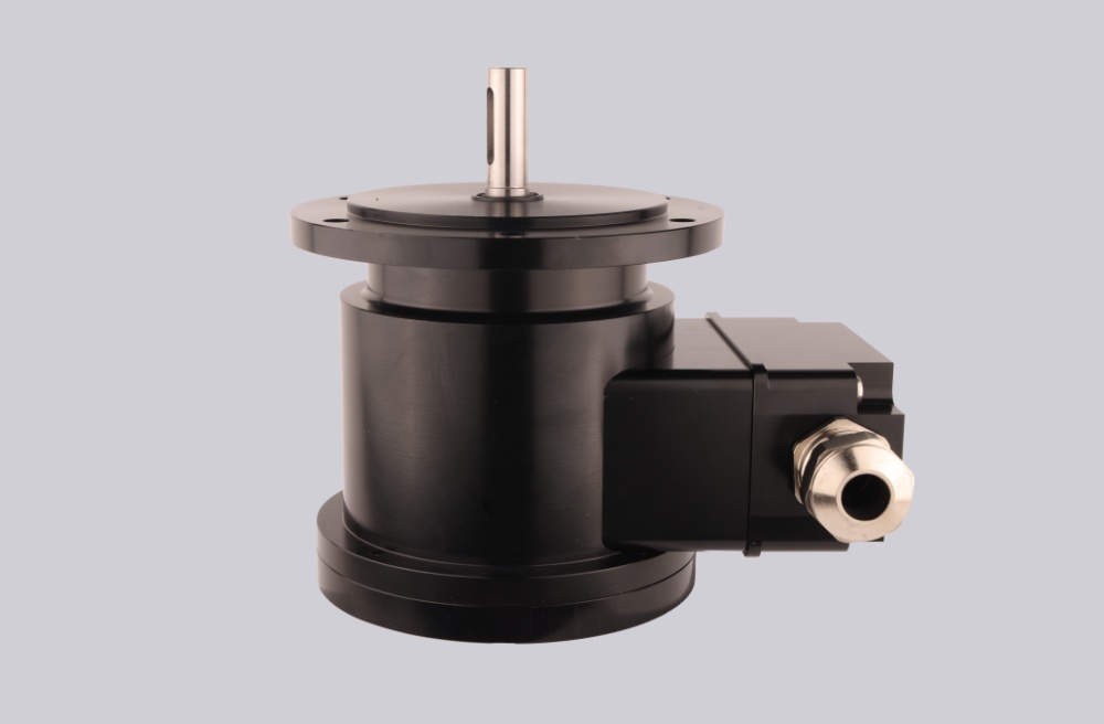
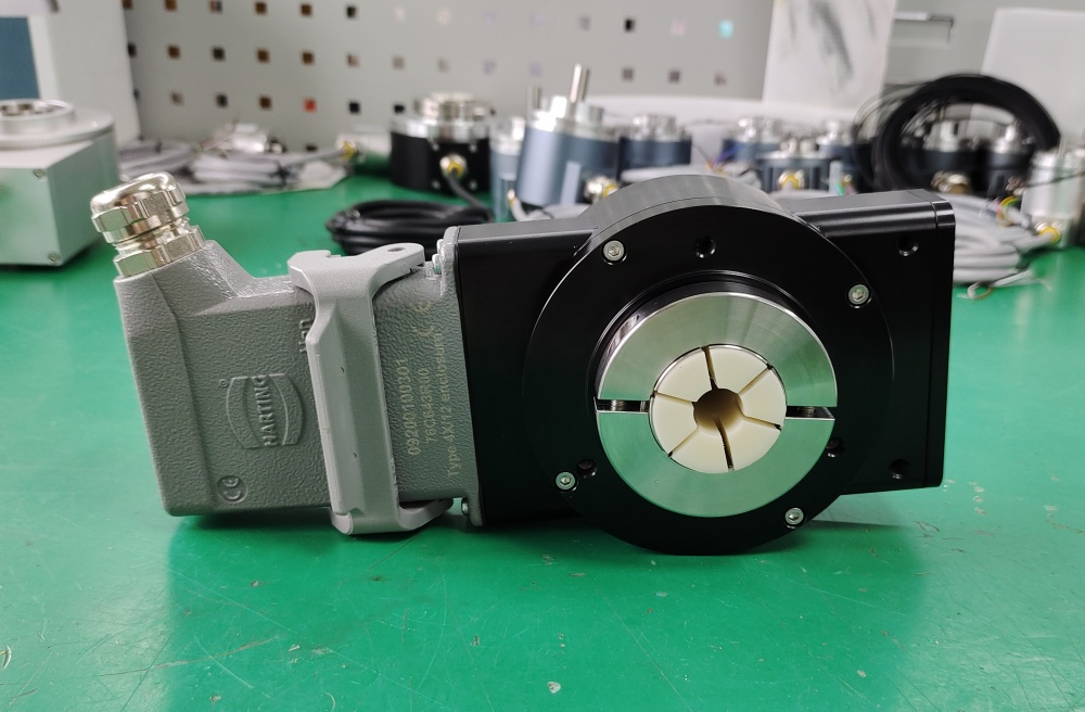
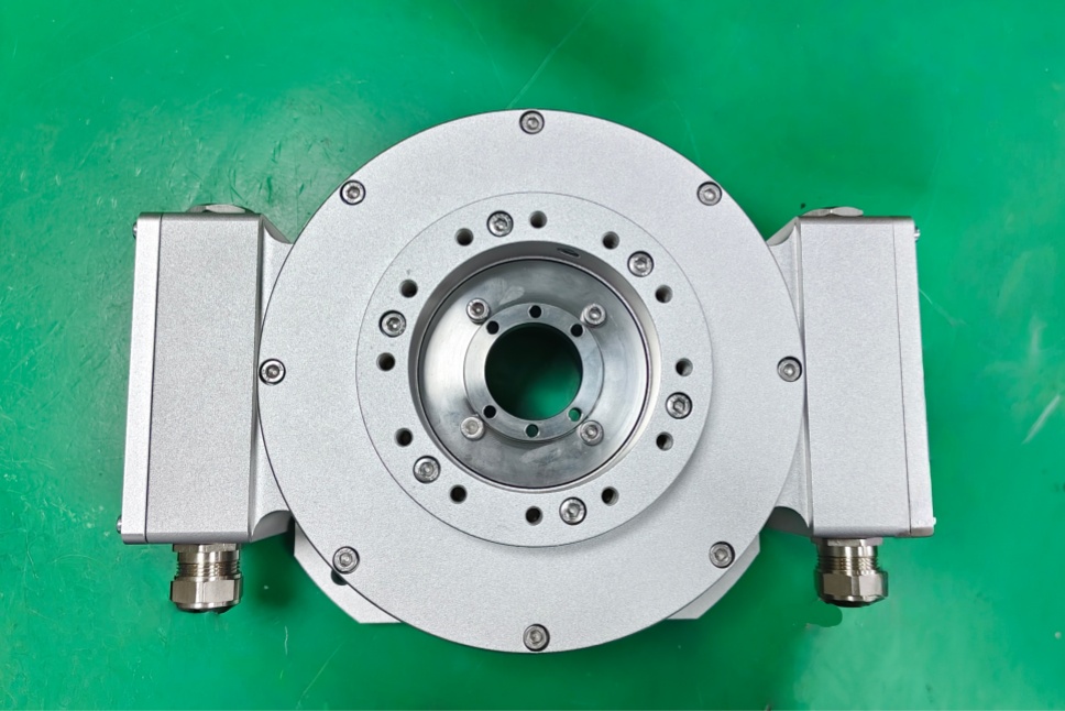
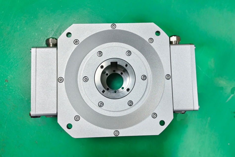
The FGH6KK-2000G-90G-NG-S-J/50P is a heavy-duty incremental encoder configuration from the FGH(I) 6 platform. In the type code, K/KK refers to terminal-box electrical connection in 1x/2x versions, while the catalog also states that SK, RK, CK, LK are versions with a second terminal box for Option S. The FGH 6 dimension drawing specifically shows the FGH 6 KK hollow-shaft version with two terminal boxes and a B14 flange for encoder attachment, and the 50P suffix identifies a Ø50 H7 hollow shaft. The code 2000G defines the pulse count, while 90G and NG indicate 90° pulse output with inverted signals and a reference pulse with inverted signal.
What makes this model different from a standard feedback-only version is the inclusion of Option S. In the FGH(I) 6 technical data, this option is listed as an additional overspeed switch, described as optional with 2 programmable switches. That means this encoder can be relevant not only for incremental speed/position feedback, but also for monitoring logic that needs switching thresholds integrated into the encoder configuration.
Industrial Integration Considerations
For this version, the engineering review should cover both the encoder feedback path and the switching function path. In many retrofit situations, the incremental output is wired into the controller, while the S-option output is tied into alarm, interlock, or overspeed supervision logic. Because of that, replacement work should confirm not only the required pulse count and supply voltage, but also how the switching output is used in the original system.
From the mechanical side, the Ø50 H7 hollow shaft is the main fitment point, and the large FGH 6 mounting geometry should be checked against the available installation space. Bore fit, torque support arrangement, flange interface, and cable routing near the dual terminal-box layout all influence whether the encoder can be installed without modification. This is especially important in heavy-duty drive assemblies where access is limited and removal time is costly.
Custom Compatible Encoder Solution
For the FGH6KK-2000G-90G-NG-S-J/50P, a custom compatible encoder solution can be arranged to match the original hollow-shaft mechanics, dual terminal-box wiring concept, incremental signal structure, and overspeed-related functional logic. The compatible design can be configured around the Ø50 shaft interface, 2000 ppr output, signal inversion requirements, reference pulse behavior, and the switching function so that the installed machine concept can remain largely unchanged.
This is particularly useful where the encoder is part of a maintenance-critical drive section and the switching output is already integrated into the machine’s protection strategy. In those cases, preserving the original operating logic is just as important as matching the mechanical mounting dimensions.
Lead Time and Custom Development
Typical production lead time: 30 working days.
Before production, the engineering review should confirm the shaft diameter, hollow-shaft fit, B14-related mounting arrangement, terminal-box layout, pulse count, output level, controller input compatibility, and the required switching behavior of the S option. The installed use of the J-coded configuration should also be checked so the compatible encoder solution can be aligned with the original site conditions and functional expectations.
Typical Technical Parameters
| Parameter | Specification |
|---|---|
| Encoder Type | Incremental encoder |
| Resolution | 2000 ppr |
| Output Type | Incremental output with overspeed switch function |
| Signal Format | 90° pulse channel with inverted signals, reference pulse with inverted signal |
| Supply Voltage | 12–30 V DC, optional 5 V DC |
| Connection Type | Terminal box connection |
| Electrical Arrangement | Two terminal boxes |
| Shaft Type | Hollow shaft |
| Shaft Diameter | Ø50 H7 |
| Mounting Feature | B14 flange for encoder attachment |
| Monitoring Function | Additional overspeed switch, optional with 2 programmable switches |
| Protection Rating | Up to IP66 |
| Operating Temperature | -25 °C to +85 °C |
| Application Orientation | Maintenance, retrofit, replacement, upgrade |