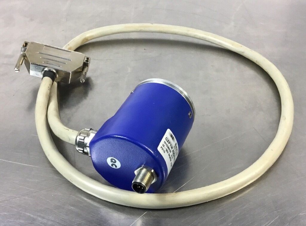
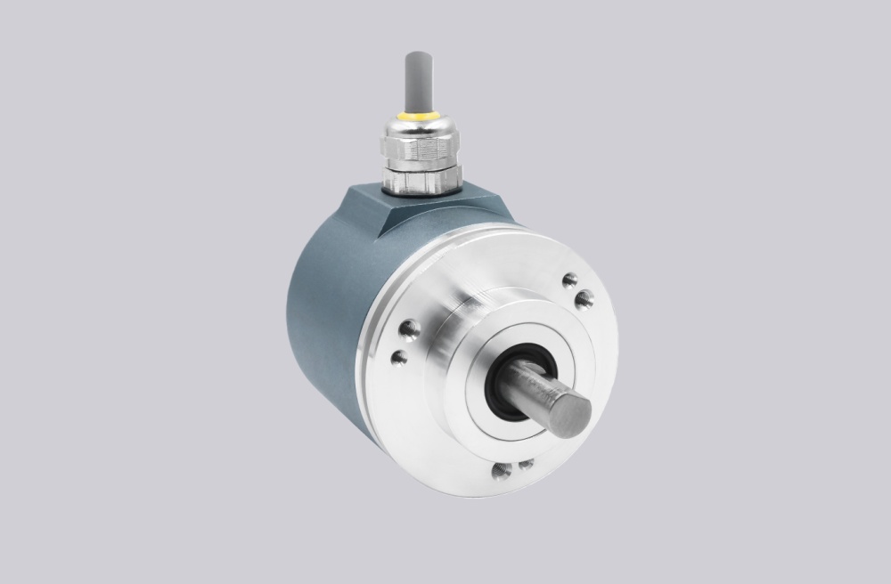
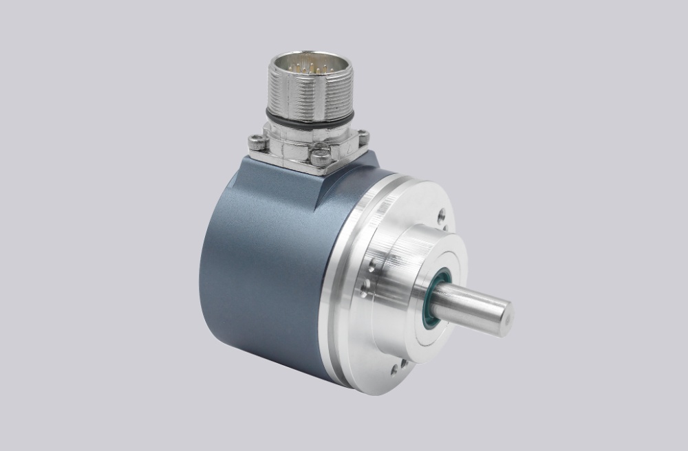
A custom compatible encoder solution can be provided for the M6C-4S1HX51ZTZ00 for maintenance, retrofit, replacement, and upgrade projects. For equipment installed in hazardous gas areas and built around an explosion-protected hollow-shaft encoder, the compatible version can be developed to match the original installation concept, with a typical production lead time of 30 working days. The M6C family is designed for CAT 2 (Zone 1) use and is marked II 2 G Ex de IIB T4 Gb, with IP66 protection and magnetoresistive sensing technology.
Technical Overview of the M6C-4S1HX51ZTZ00 Encoder
The M6C-4S1HX51ZTZ00 belongs to the M6C explosion-protected hollow-shaft incremental encoder family. Within this platform, M6C-4 identifies the 1-inch hollow-shaft version. The series can be equipped with one or two electrically independent and totally isolated outputs, and the outputs can be wired as single ended single phase, single ended two phase (A,B), or differential (A quad B). The family provides incremental square-wave signals with A, A-, B, B-, Z, Z- channels and supports demanding industrial control and instrumentation applications.
For this batch of models, the pulse count is to be treated as 1024 ppr. That aligns well with the M6C family architecture, which allows output resolution to be determined by the rotor base PPR and sensor multiplier, and also supports extended resolutions beyond the base values. The M6C platform supports output frequencies from 0 to 250 kHz and is intended for hazardous-location use where stable incremental feedback and sealed enclosure performance are both required.
Industrial Integration Considerations
For this model, the first engineering checkpoint is the combination of hazardous-area compliance and hollow-shaft fit. The M6C uses a hollow shaft, clamping collar, and anti-rotation bracket, and the manual makes clear that the encoder should not be rigidly mounted. The standard flexible anti-rotation bracket can tolerate ±0.1 inch shaft end float, which is important when matching the encoder to an existing motor or driven shaft. Installation should also verify shaft condition, burr-free engagement, and runout behavior before the replacement is finalized.
Electrical integration should also be reviewed carefully. The M6C manual states that cable entry devices used in the increased-safety enclosure must be correctly certified and installed, unused apertures must be closed with certified blanking elements, and wiring must be suitable for the actual ambient range. In addition, the housing must be grounded at the specified points, and the encoder must not be opened in a hazardous environment while energized. These are practical issues that directly affect retrofit reliability in Zone 1 installations.
Custom Compatible Encoder Solution
For the M6C-4S1HX51ZTZ00, a custom compatible encoder solution can be engineered to match the original hazardous-area installation concept as closely as possible. The compatible version can be configured around the required 1-inch bore, 1024 ppr output, marker requirement, connection arrangement, anti-rotation mounting logic, and explosion-protection level so that surrounding machine modification remains limited during replacement.
This is especially useful where the encoder is already installed in a Zone 1 gas environment and where field changes to conduit entry, mounting geometry, or control wiring would increase service risk. In those cases, the practical objective is not only mechanical replacement, but continuity in signal behavior, enclosure suitability, and installation handling under hazardous-location requirements.
Custom Solution Photos


Lead Time and Custom Development
Typical production lead time: 30 working days.
Before production, the engineering review should confirm the shaft size, pulse requirement, marker configuration, output arrangement, connection style, hazardous-area installation conditions, grounding method, and controller input expectations. Special attention should be given to the exact coded options in the model number so the compatible solution can be aligned with the installed encoder rather than only with the general series specification.
Typical Technical Parameters
| Parameter | Specification |
|---|---|
| Encoder Type | Explosion-protected incremental hollow-shaft encoder |
| Resolution | 1024 ppr |
| Series | M6C-4 |
| Hazardous Area Classification | CAT 2 (Zone 1) |
| Explosion Protection Marking | II 2 G Ex de IIB T4 Gb |
| Sensing Principle | Magnetoresistive |
| Shaft Type | Hollow shaft |
| Shaft Diameter | 1 inch |
| Output Channels | A, A-, B, B-, Z, Z- |
| Signal Type | Incremental square wave |
| Output Frequency | 0 to 250 kHz |
| Output Arrangement | One or two isolated outputs, depending on configuration |
| Protection Rating | IP66 |
| Max Speed | Up to 5000 RPM |
| Operating Temperature | -20 °C to +80 °C, or -40 °C to +80 °C with modification code 001 or 005 |
| Application Orientation | Maintenance, retrofit, replacement, upgrade |

