For systems using the M6C-4S8HX51ZTZ00, a custom compatible encoder solution can be engineered for maintenance support, retrofit execution, replacement planning, and upgrade work. Where the installed machine operates in a hazardous gas area and already uses an explosion-protected hollow-shaft encoder with a defined marker arrangement, the compatible version can be developed around the original shaft fit, signal structure, and enclosure concept, with a typical production lead time of 30 working days.
Technical Overview of the M6C-4S8HX51ZTZ00 Encoder
The M6C-4S8HX51ZTZ00 belongs to the M6C explosion-protected hollow-shaft incremental encoder family for hazardous-duty industrial environments. This series is designed for CAT 2 (Zone 1) use and carries the marking II 2 G Ex de IIB T4 Gb, with IP66 enclosure protection and magnetoresistive sensing technology. Within the family structure, M6C-4 identifies the 1-inch hollow-shaft version. The platform supports one or two electrically independent and totally isolated outputs and provides incremental square-wave feedback through A, A-, B, B-, Z, Z- channels.
For this batch of models, the pulse count is to be treated as 1024 ppr. This specific model includes the 8 line-driver code. In the M6C coding table, 8 corresponds to a 5 to 24 VDC line-driver arrangement. The model also includes a Z marker-related code in its type structure. In the M6C coding table, Z identifies a marker version, while K is used for a different sync-marker arrangement. Because this model includes additional coded suffix elements beyond the standard family blocks, those details should be matched directly to the installed unit during engineering review so the compatible design preserves the original field configuration.
Industrial Integration Considerations
For this version, the main electrical checkpoint is the compatibility of the 5 to 24 VDC line-driver arrangement with the receiving control hardware, together with the marker-handling logic used by the controller. During retrofit work, the available supply range, controller input acceptance, shielding continuity, and signal-path stability should all be reviewed before finalizing the compatible solution. Since the M6C family supports incremental output up to 250 kHz, transmission quality should be checked directly, especially where cable length, grounding condition, or site interference may influence reliable operation.
Mechanically, the 1-inch hollow shaft remains the primary fitment point. The M6C installation guidance states that the encoder must not be rigidly mounted and should use the intended hollow-shaft, clamping-collar, and anti-rotation bracket concept. The standard flexible anti-rotation bracket can tolerate ±0.1 inch shaft end float, and shaft runout should be checked before the compatible replacement is finalized. In hazardous-area service, enclosure integrity, grounding points, and correct closure of unused openings are also part of the installation review.
Custom Compatible Encoder Solution
For the M6C-4S8HX51ZTZ00, a custom compatible encoder solution can be configured to match the original explosion-protected installation concept as closely as possible. The compatible version can be aligned with the required 1-inch bore, 1024 ppr output, 5 to 24 VDC line-driver structure, marker requirement, output arrangement, and hazardous-area rating so that surrounding machine changes remain limited during replacement.
This is especially useful where the encoder is already installed in a Zone 1 environment and where the control system depends on both incremental feedback and a defined marker signal structure. In those cases, the practical objective is to preserve shaft fit, signal continuity, enclosure suitability, and commissioning logic together.
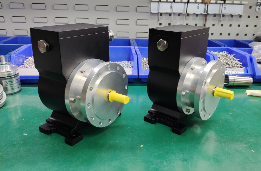
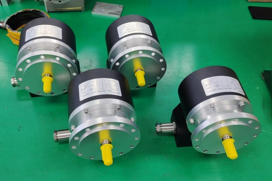
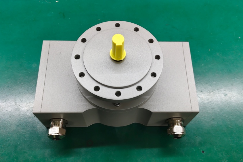
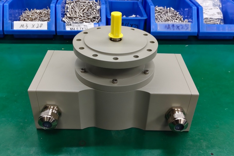
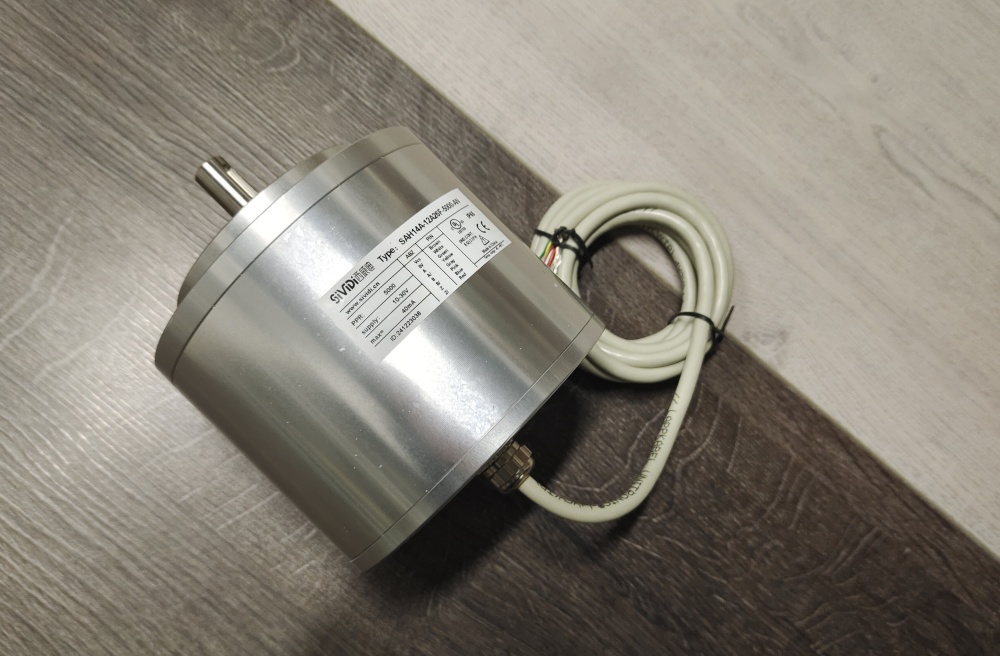
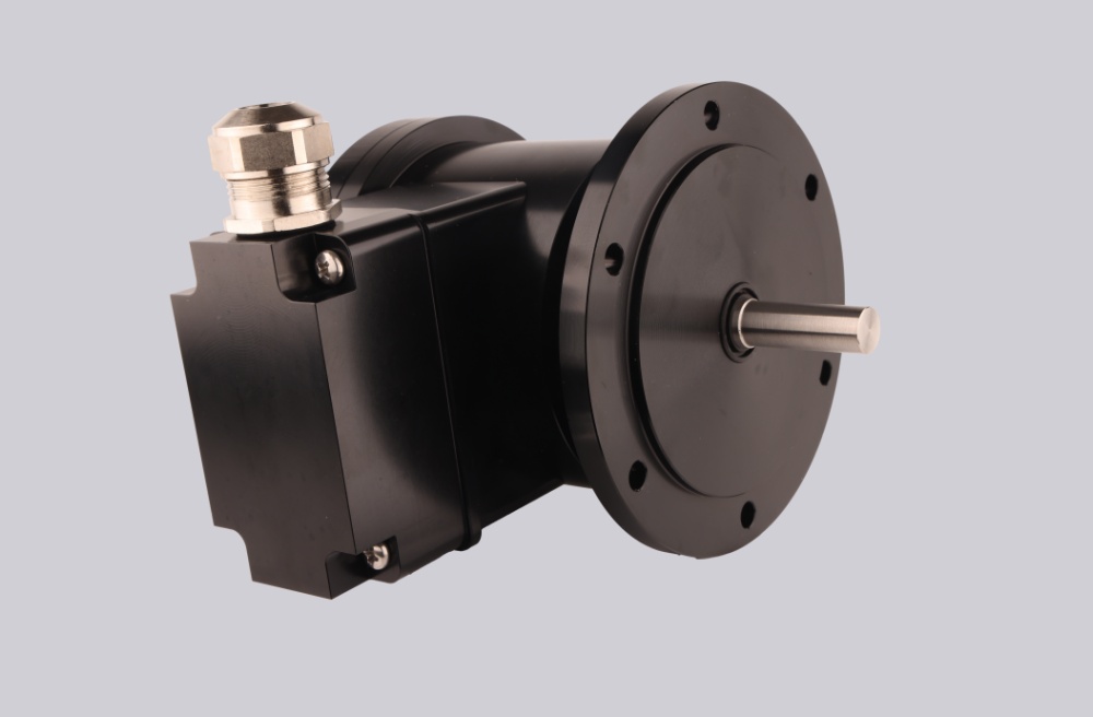
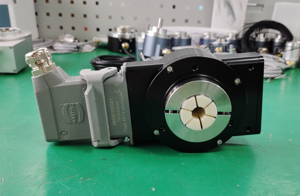
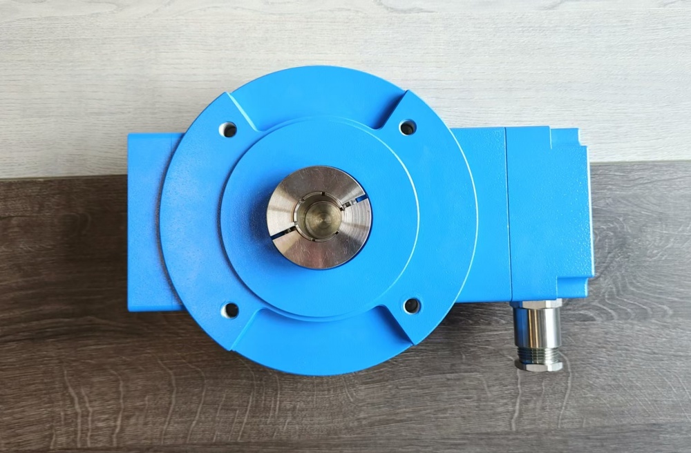
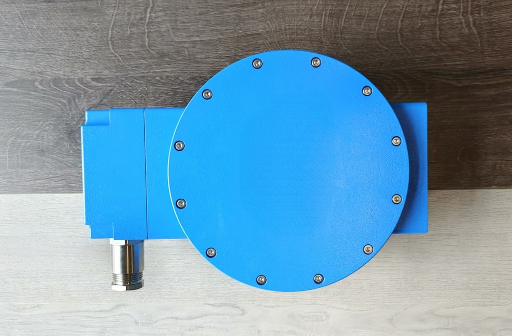
Custom Solution Photos
Lead Time and Custom Development
Typical production lead time: 30 working days.
Before production, the engineering review should confirm the shaft size, pulse requirement, line-driver supply range, output arrangement, marker requirement, hazardous-area installation conditions, grounding method, and controller input expectations. The complete coded structure should also be checked against the installed unit so the compatible solution can remain consistent with the actual field configuration.
Typical Technical Parameters
| Parameter | Specification |
|---|---|
| Encoder Type | Explosion-protected incremental hollow-shaft encoder |
| Resolution | 1024 ppr |
| Series | M6C-4 |
| Hazardous Area Classification | CAT 2 (Zone 1) |
| Explosion Protection Marking | II 2 G Ex de IIB T4 Gb |
| Sensing Principle | Magnetoresistive |
| Shaft Type | Hollow shaft |
| Shaft Diameter | 1 inch |
| Output Channels | A, A-, B, B-, Z, Z- |
| Signal Type | Incremental square wave |
| Output Frequency | 0 to 250 kHz |
| Line Driver Supply Range | 5 to 24 VDC |
| Marker Option | Z marker configuration |
| Output Arrangement | One or two isolated outputs, depending on configuration |
| Protection Rating | IP66 |
| Max Speed | Up to 5000 RPM |
| Operating Temperature | -20 °C to +80 °C, or -40 °C to +80 °C with modification code 001 or 005 |
| Application Orientation | Maintenance, retrofit, replacement, upgrade |