A custom compatible encoder solution can be provided for the 14-14361-5000 and 14-14361-1024 for maintenance, retrofit, replacement, and upgrade projects. Where the installed equipment uses this incremental rotary encoder platform in mechanically demanding industrial environments, the compatible version can be developed around the original flange geometry, shaft-side pulley arrangement, and cable connection concept, with a typical production lead time of 15 working days.
Technical Overview of the 14-14361-5000 and 14-14361-1024 Encoder
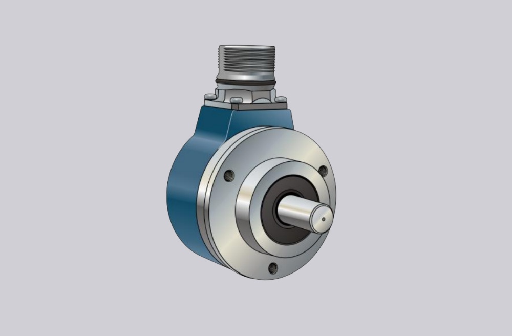
The 14-14361-5000 and 14-14361-1024 belong to the same incremental rotary encoder platform designed for applications with high mechanical demand. This series uses photoelectric sampling and supports pulse counts up to 5000 ppr. In this paired configuration, the main technical difference lies in the pulse count: one model is configured with 5000 ppr, while the other uses 1024 ppr. The electrical platform remains the same, with 10 to 30 V DC supply, short-circuit-proof push-pull output, complementary signal channels A, A-, B, B-, 0, 0-, a maximum output frequency of 100 kHz, and a fixed 9-core cable, 2 m connection.
From the mechanical side, both models share the same core construction. The housing and flange are made of aluminum, the shaft is stainless steel 1.4305 / AISI 303, and the shaft includes a feather key groove for pulley installation. The mounting design also uses Ø40 mm and Ø80 mm centering features together with 3 × M6 fixing points. This common platform makes it practical to handle these two variants together in one engineering solution page, because the installation concept remains consistent while the signal resolution changes according to control requirements.
Industrial Integration Considerations
For these two models, the main integration difference is on the controller side. The 14-14361-1024 is more suitable where the installed system uses a moderate-resolution feedback structure with lower signal density and straightforward evaluation logic. The 14-14361-5000 is more relevant where the machine requires much finer rotational subdivision and more detailed speed or position feedback. In retrofit work, the receiving controller, counter input, or speed-evaluation module should therefore be checked carefully for pulse-count compatibility, frequency-processing capacity, shielding continuity, and reference-channel handling before the replacement is finalized.
Mechanically, both variants should be reviewed in the same way. The encoder platform is intended for higher mechanical demand and includes a shaft with feather key groove for pulley installation. Pulley alignment, shaft-side load, radial and axial force, and mounting-face compatibility should all be confirmed before production so the compatible solution remains consistent with the installed machine layout. The documented limits include 60 N axial load, 80 N radial load, and a maximum speed of 6000 min⁻¹.
Custom Compatible Encoder Solution
For the 14-14361-5000 and 14-14361-1024, a custom compatible encoder solution can be engineered around the same mechanical installation platform while matching different signal-resolution requirements. The compatible version can be aligned with the required 5000 ppr or 1024 ppr output, push-pull signal structure, flange and centering geometry, shaft-side pulley arrangement, and cable connection concept so that surrounding machine changes remain limited during replacement.
This combined approach is especially useful where the installed equipment family uses the same encoder platform across different control configurations. In those cases, the practical objective is to preserve mechanical interchangeability and installation continuity while selecting the pulse count that matches the original control logic.
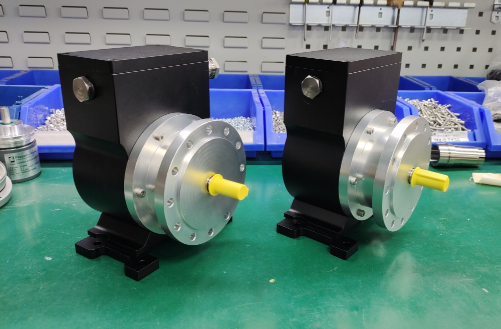
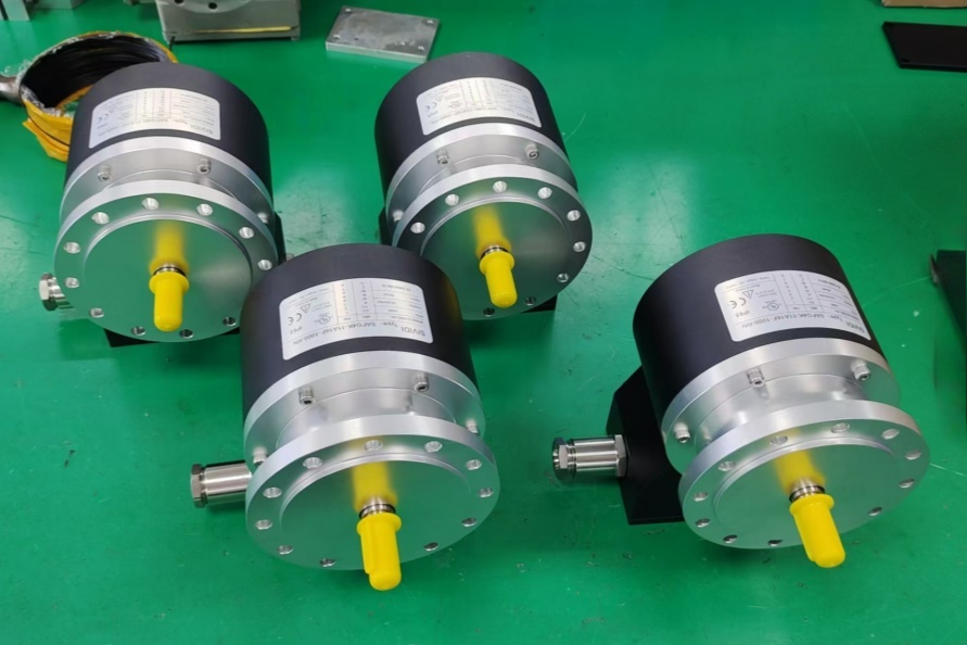
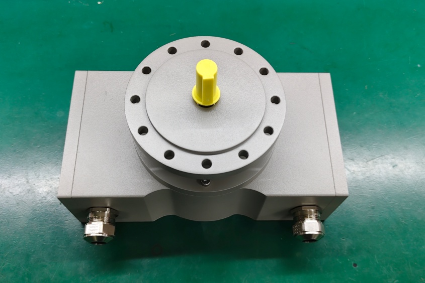
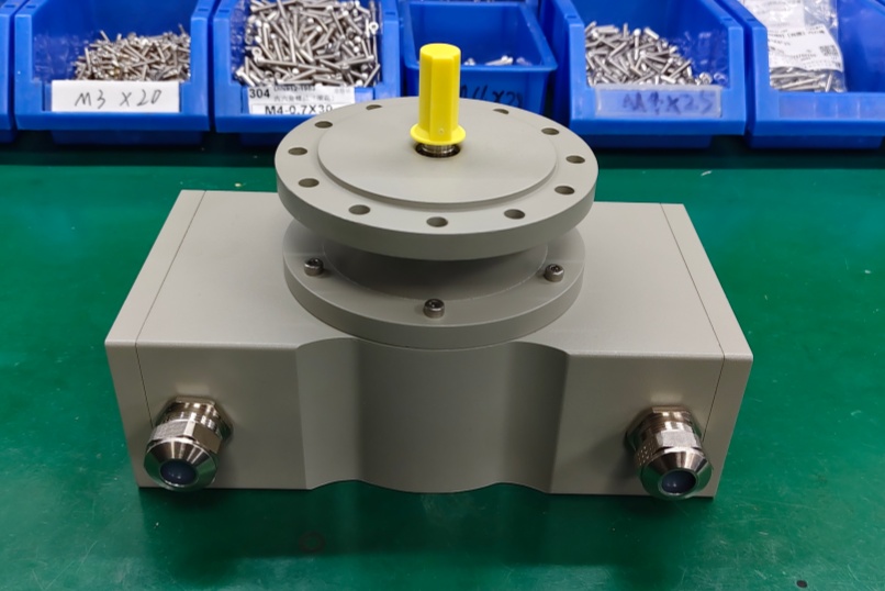
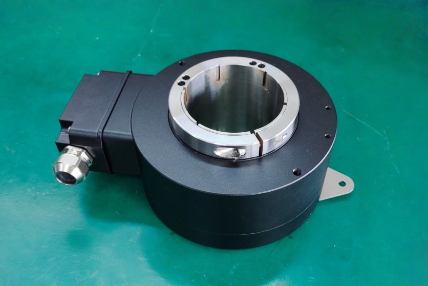
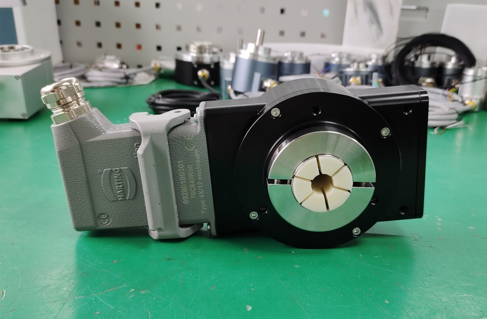
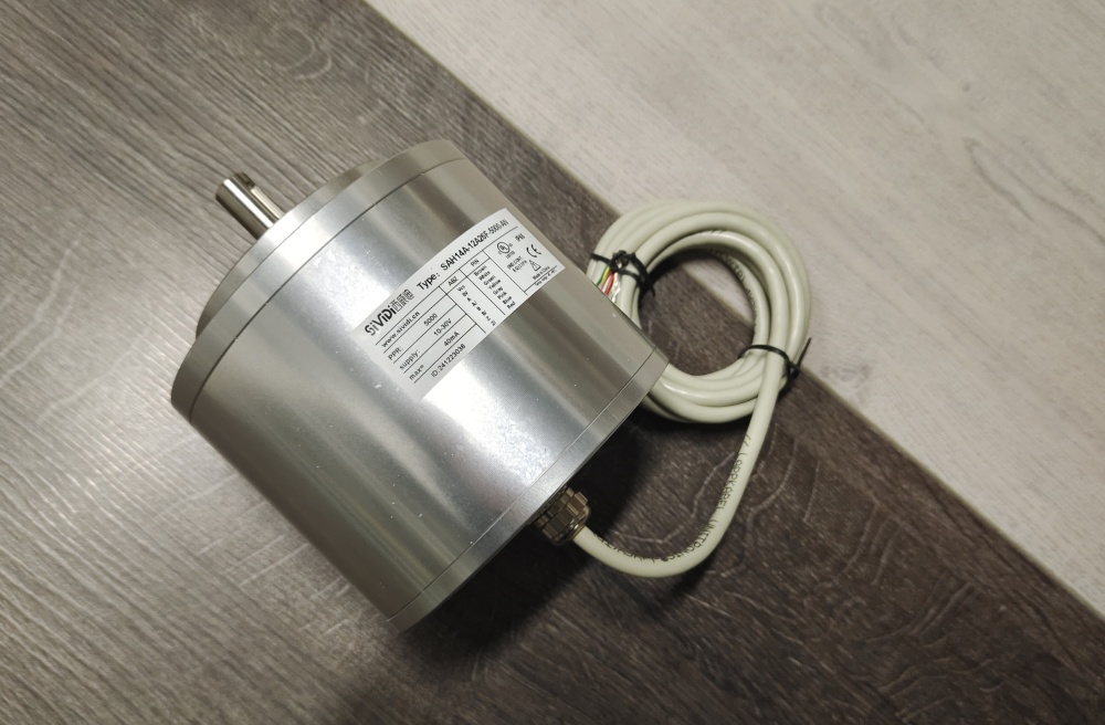
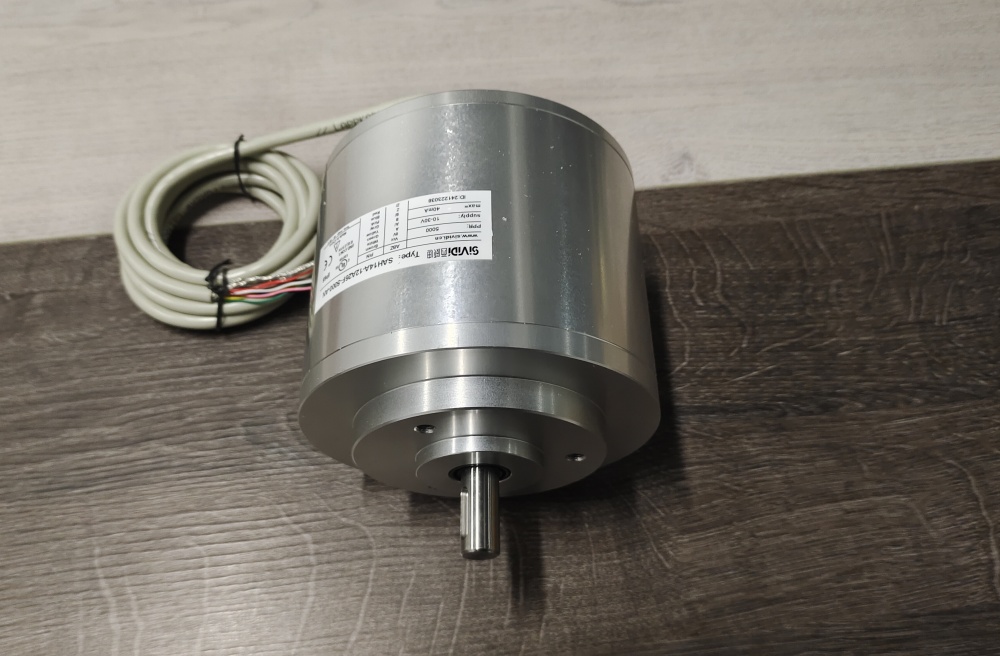
Custom Solution Photos
Lead Time and Custom Development
Typical production lead time: 15 working days.
Before production, the engineering review should confirm which pulse count is required, the output type, supply voltage, cable connection requirements, flange and centering dimensions, shaft and pulley arrangement, installation conditions, and controller input expectations. Environmental temperature limits and enclosure requirements should also be checked against the actual site conditions so the compatible solution can be matched to the working environment. The series documentation also includes ATEX approval and flameproof enclosure data where the installed application requires those characteristics.
Typical Technical Parameters
| Parameter | 14-14361-5000 | 14-14361-1024 |
|---|---|---|
| Encoder Type | Incremental rotary encoder | Incremental rotary encoder |
| Resolution | 5000 ppr | 1024 ppr |
| Sensing Principle | Photoelectric sampling | Photoelectric sampling |
| Output Type | Push-pull incremental output | Push-pull incremental output |
| Signal Format | A, A-, B, B-, 0, 0- | A, A-, B, B-, 0, 0- |
| Supply Voltage | 10 to 30 V DC | 10 to 30 V DC |
| No-Load Current | Max. 80 mA | Max. 80 mA |
| Max. Output Frequency | 100 kHz | 100 kHz |
| Connection Type | 9-core cable, 2 m | 9-core cable, 2 m |
| Protection Rating | IP66 | IP66 |
| Max. Speed | 6000 min⁻¹ | 6000 min⁻¹ |
| Shaft Material | Stainless steel 1.4305 / AISI 303 | Stainless steel 1.4305 / AISI 303 |
| Housing / Flange Material | Aluminum | Aluminum |
| Axial Load | 60 N | 60 N |
| Radial Load | 80 N | 80 N |