The FGH6KK-2500G-90G-NG-S-J/50P can be supported with a custom compatible encoder solution for maintenance planning, retrofit execution, equipment replacement, and system upgrade tasks. For projects that need to retain the original hollow-shaft arrangement and monitoring logic, the compatible version can be developed around the installed mechanical and electrical conditions, with a normal production lead time of 30 working days.
Technical Overview of the FGH6KK-2500G-90G-NG-S-J/50P Encoder
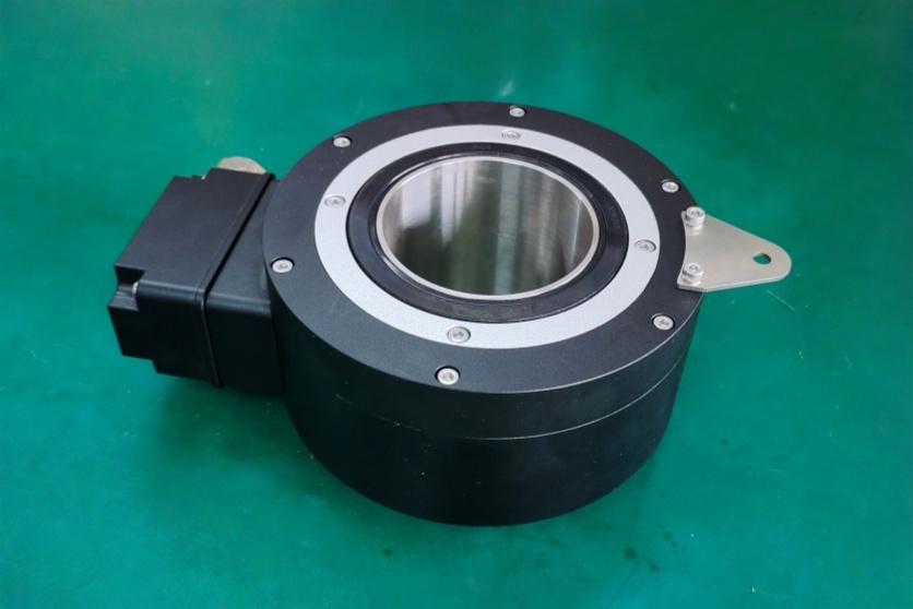
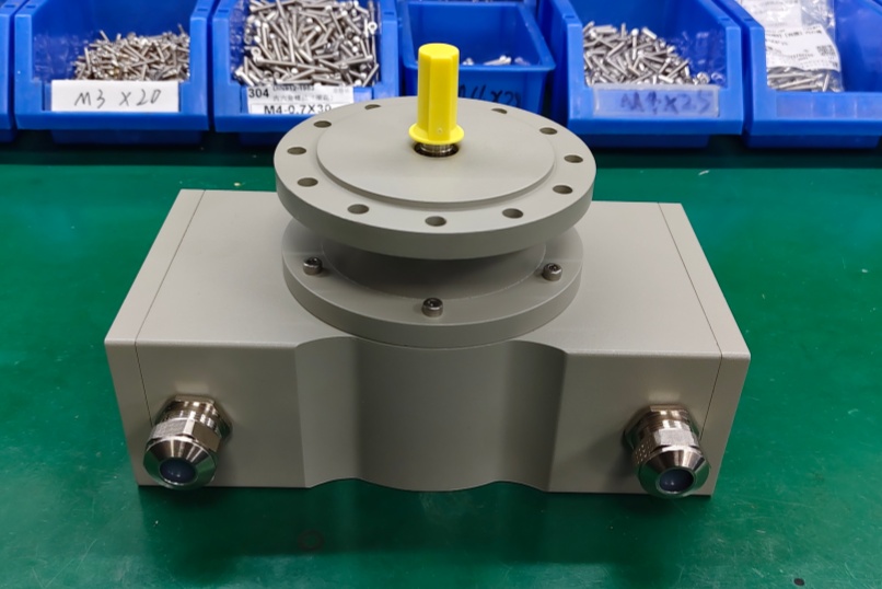
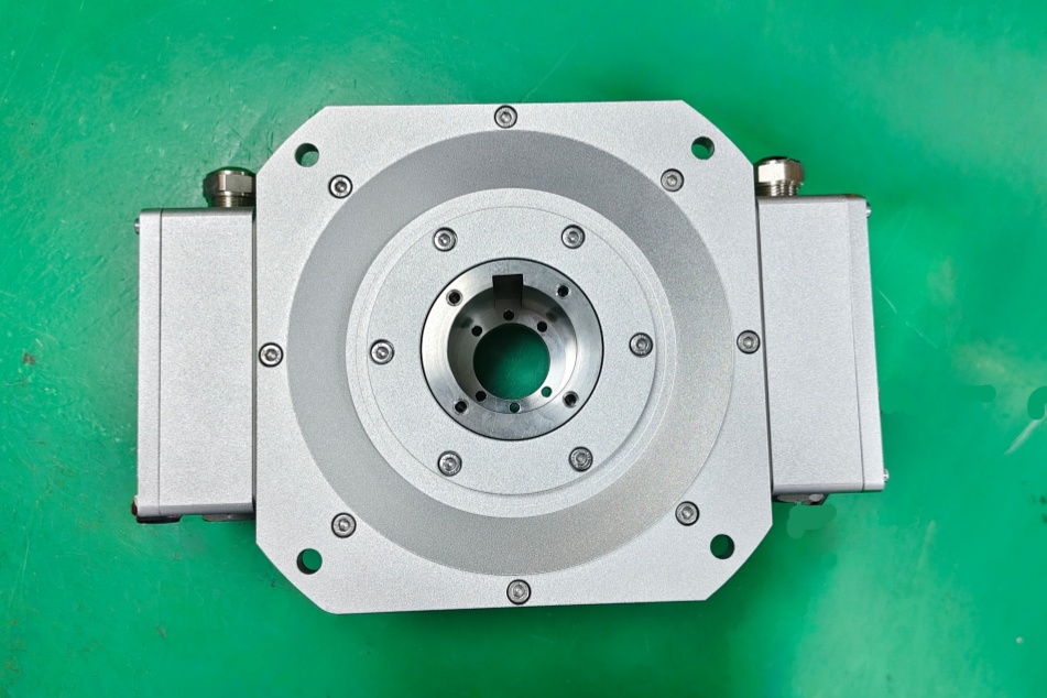
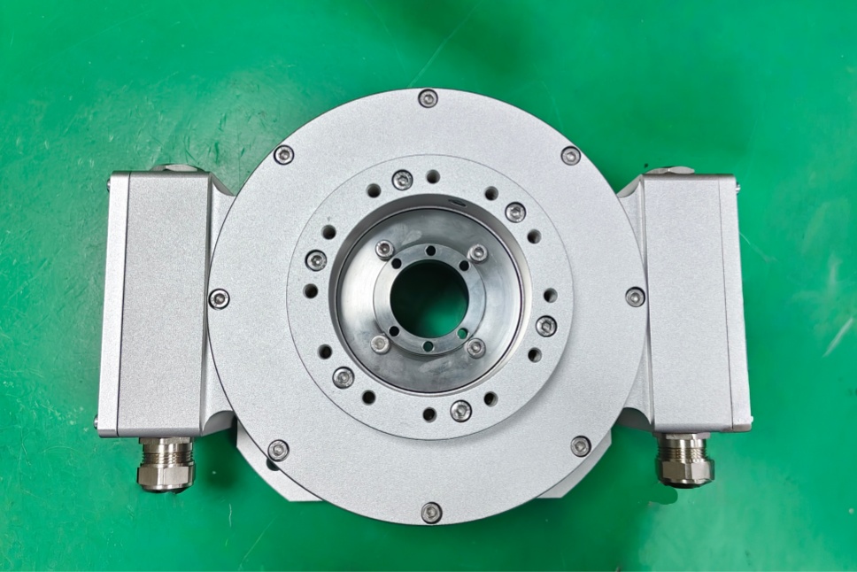
This model belongs to the FGH 6 heavy-duty incremental encoder platform and combines several coded features that make it distinct within the series. The 2500G section defines the pulse count, while 50P identifies a Ø50 H7 hollow shaft configuration. The KK code corresponds to a version with two terminal boxes, which is especially relevant here because the catalog states that this arrangement is used for versions equipped with Option S. The 90G / NG coding indicates quadrature-style pulse output with inverted signals and a reference pulse with inverted reference signal.
What clearly differentiates this configuration is the presence of Option S, which the catalog defines as an electronic overspeed switch. In the FGH(I) 6 documentation, this option is described with two independently programmable switching points and associated monitoring functions, making it relevant not only for feedback generation but also for speed-related protective or supervisory logic within the machine system.
Industrial Integration Considerations
For this encoder version, integration work should not focus only on shaft fit and pulse count. Because the model includes an electronic overspeed switching function, the project review should also confirm how the existing system uses that speed-monitoring output. In practice, that means checking whether the original installation applies the switching signal for alarm logic, speed supervision, shutdown interlock, or other protective control functions.
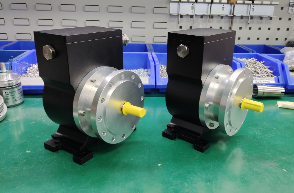
From the mechanical side, the Ø50 hollow shaft remains a critical fitment point. Shaft surface condition, bore fit, anti-rotation support, and available mounting space should all be verified before installation. The dual terminal-box arrangement also affects cable segregation and service access, especially where one wiring path is used for encoder feedback and another is tied to monitoring or switching functions.
Custom Compatible Encoder Solution
For the FGH6KK-2500G-90G-NG-S-J/50P, a custom compatible encoder solution can be configured to match both the feedback side and the speed-monitoring side of the installed system. The compatible design can be aligned with the required Ø50 H7 hollow shaft, pulse count, signal structure, terminal-box arrangement, and overspeed-related functional logic so that the existing machine concept can be preserved with minimal rework.
This is particularly important in retrofit projects where the encoder does more than provide position or speed pulses. If the installed machine relies on the S-option switching behavior as part of its operating sequence, that function must be reviewed during engineering and reproduced correctly in the compatible solution rather than treated as a secondary detail.
Lead Time and Custom Development
Typical production lead time: 30 working days.
Before production, the engineering review should confirm the hollow-shaft size, mounting method, pulse requirement, supply voltage, signal format, terminal-box arrangement, and the exact use of the overspeed switching function in the machine. The switching thresholds, output expectations, and integration with the existing control logic should be checked in advance so the compatible encoder solution can be prepared without functional ambiguity.
Typical Technical Parameters
| Parameter | Specification |
|---|---|
| Encoder Type | Incremental encoder |
| Resolution | 2500 ppr |
| Output Type | Incremental output with overspeed switch function |
| Signal Format | 90° pulse channel with inverted signals, reference pulse with inverted signal |
| Supply Voltage | 12–30 V DC, optional 5 V DC |
| Connection Type | Terminal box connection |
| Electrical Arrangement | Two terminal boxes |
| Shaft Type | Hollow shaft |
| Shaft Diameter | Ø50 H7 |
| Monitoring Function | Electronic overspeed switch |
| Protection Rating | Up to IP66 |
| Operating Temperature | -25 °C to +85 °C |
| Option Code | S and J options included |
| Application Orientation | Maintenance, retrofit, replacement, upgrade |