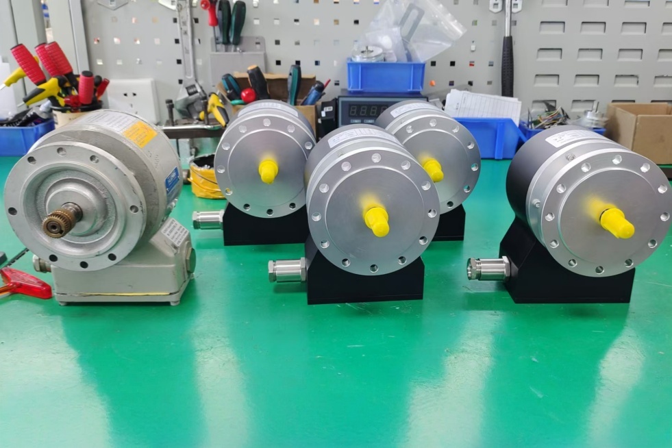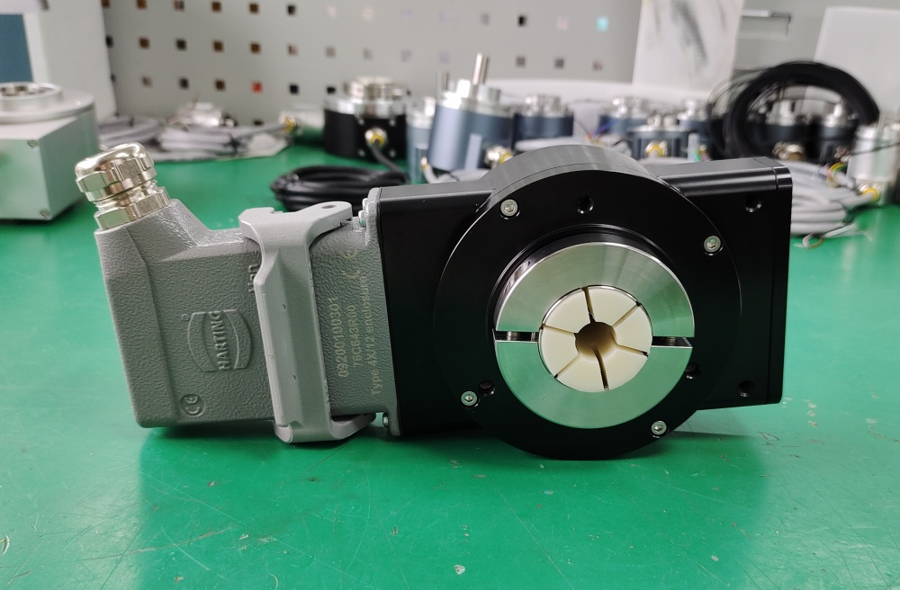


The FG40KK-1200G-90G-NG and FG40KK-16384G-90G-NG are heavy-duty encoders belonging to the FGH40KK product series. Both models are excellent encoders and are often found in applications at steel mills or chemical plants.
Today, I will document the alternative product solutions for these two encoders.
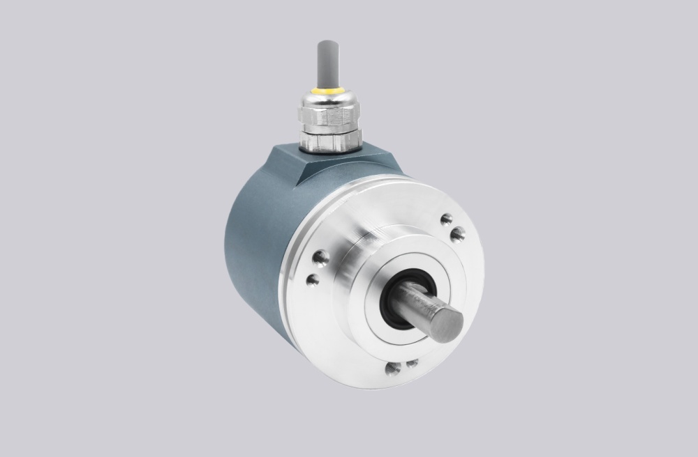
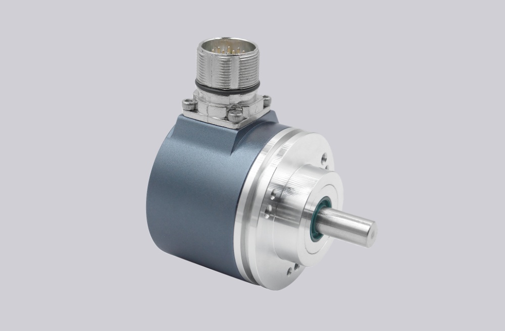
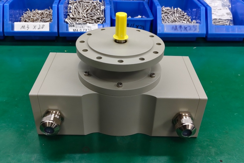
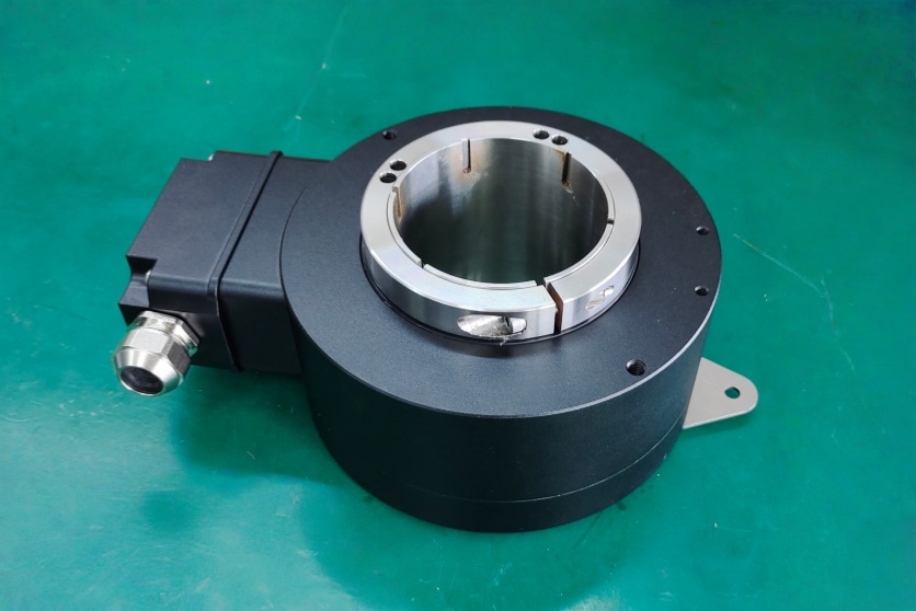
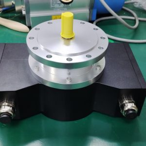
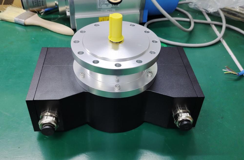
The FG40KK series features a dual terminal box design with a flange size of 115mm and a shaft diameter of 11mm (with some exceptions at 14mm). The difference between various products lies in the pulse count. For instance, these two models have pulse counts of 1200ppr and 16384ppr, respectively.
The 16384ppr product is particularly memorable due to its high pulse count, which is uncommon in applications. I recall providing one to an electrical engineering department at a university. The majority of the applications have been in steel mills, with some in coal chemical enterprises. For exports, Russia accounts for a significant portion, followed by the Middle East, Latin America, and Southeast Asia.

While there are many countries we export to, the order quantities are not substantial. Procurement for such products is inherently in small volumes, typically three, five, or ten to eight units.
Originally, this product was not our main focus, as the procurement volume was too low. It is a custom-made product developed as an alternative solution under the commission of steel enterprise clients. Subsequently, it was introduced as a service to address procurement challenges.
Previously, we did not publicize this information. As more people became aware, there were complaints that we did not release the news earlier. Prior to this, we were unaware of the difficulties in procuring the original product and the extended delivery times.
Upon learning this information, I began to document these procurement challenges and alternative solutions through blog posts. In the first two entries, I expressed gratitude to Mr. Sergey for his encouragement.
This blog will continue, currently focusing on documenting encoders that are difficult to procure. If I have the capacity, I will later record some standard products as well.
That concludes today's entry. Good luck to all!
If you need assistance, please feel free to send me a message.