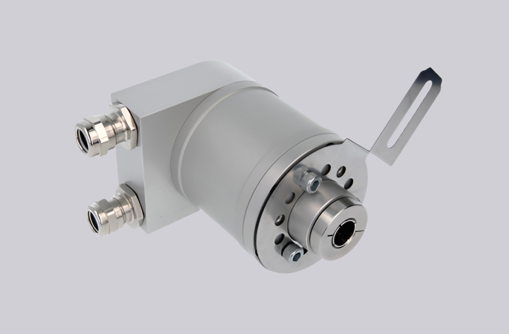
The 8.9080.4331.3001 encoder can be supported through a custom compatible solution for replacement, retrofit, maintenance, and upgrade projects. This coded version uses a 20 mm through hollow shaft, mounting flange, and cable gland terminal box arrangement on a multiturn PROFIBUS DP absolute encoder platform. Typical production lead time: 15 working days. The engineering focus for this model is to preserve mounting flange alignment and 20 mm shaft fit while maintaining the original fieldbus communication behavior.
Technical Overview of the 8.9080.4331.3001 Encoder
This encoder belongs to a PROFIBUS DP multiturn family with binary coding, RS485 physical layer, and scalable absolute resolution. The platform supports programmable rotation direction, preset value, diagnostics mode, and scaling parameters, which makes it suitable for integration into established control architectures already using profile-based position data handling.
In this version, the order code resolves to flange type 4 and shaft code 3, meaning a mounting flange with a 20 mm H7 through hollow shaft. Connection code 1 identifies the removable terminal cover with cable gland M16. That combination is often chosen where the installation prefers firm flange location and enclosed terminal wiring rather than external connector-based routing.
Industrial Integration Considerations
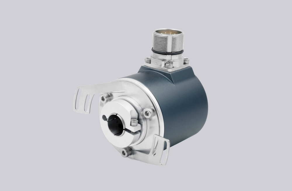
Compared with spring-element versions, a mounting flange encoder is usually more sensitive to exact axial and radial alignment during retrofit work. That does not make it less suitable, but it means the original shaft engagement length, flange surface condition, and housing reference position should be reviewed before replacement is finalized. For this specific model, the 20 mm H7 bore is a primary compatibility parameter.
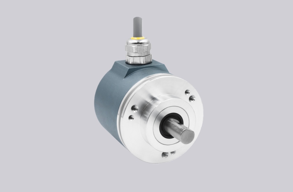
The cable gland construction also influences field service practice. Since terminal-box versions can simplify sealed cable entry and direct wire termination, they are often kept in place during retrofit projects to avoid changing plant-level wiring conventions. Matching this connection style is therefore part of practical engineering compatibility, not merely a cosmetic detail.
Custom Compatible Encoder Solution
A compatible replacement solution for 8.9080.4331.3001 should be built around three points: the 20 mm through hollow shaft, the mounting flange arrangement, and the cable gland terminal cover. On the electrical side, the solution should preserve PROFIBUS DP class 2 behavior, scalable resolution structure, and the same supply category of 10 ... 30 V DC. On the mechanical side, it should remain suitable for the original flange-based installation logic so that field adaptation work stays limited.
Where original machine data handling depends on preset, total resolution scaling, or directional conventions, those configuration items should be matched during engineering review before the final replacement configuration is released.
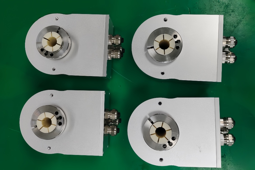
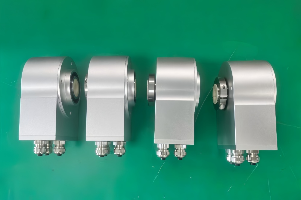
Custom Solution Photos
Lead Time and Custom Development
Typical production lead time: 30 working days.
Custom development for this model should verify flange-side mounting dimensions, shaft bore tolerance, cable entry requirements, and controller-side PROFIBUS settings. This helps maintain commissioning continuity and avoids avoidable site changes during encoder replacement.
Typical Technical Parameters
| Parameter | Specification |
|---|---|
| Encoder Type | Multiturn absolute encoder |
| Model | 8.9080.4331.3001 |
| Interface | PROFIBUS DP |
| Protocol Profile | Class 2 |
| Physical Layer | RS485 |
| Supply Voltage | 10 ... 30 V DC |
| Resolution Singleturn | 1 ... 8192, scalable |
| Multiturn Capability | 1 ... 4096, scalable |
| Max Overall Resolution | 25 bit |
| Code Type | Binary |
| Shaft Type | Through hollow shaft |
| Bore Size | 20 mm H7 |
| Mounting Style | Mounting flange |
| Connection Type | Removable bus terminal cover with cable gland M16 |
| Protection Rating | IP65 |
| Operating Temperature | -10°C ... +70°C |
| Max. Speed | 6000 min⁻¹ max., 3000 min⁻¹ continuous |