Custom engineering support is available for BMA 3G.24C8192-C6-4 for maintenance, retrofit, replacement, and upgrade requirements. Typical production lead time: 15 working days. In systems where the original encoder is installed with axial cable routing, a custom compatible solution can be engineered to preserve the existing cable path, servo flange fit, and SSI control continuity while reducing modification work during replacement.
Technical Overview of the BMA 3G.24C8192-C6-4 Encoder
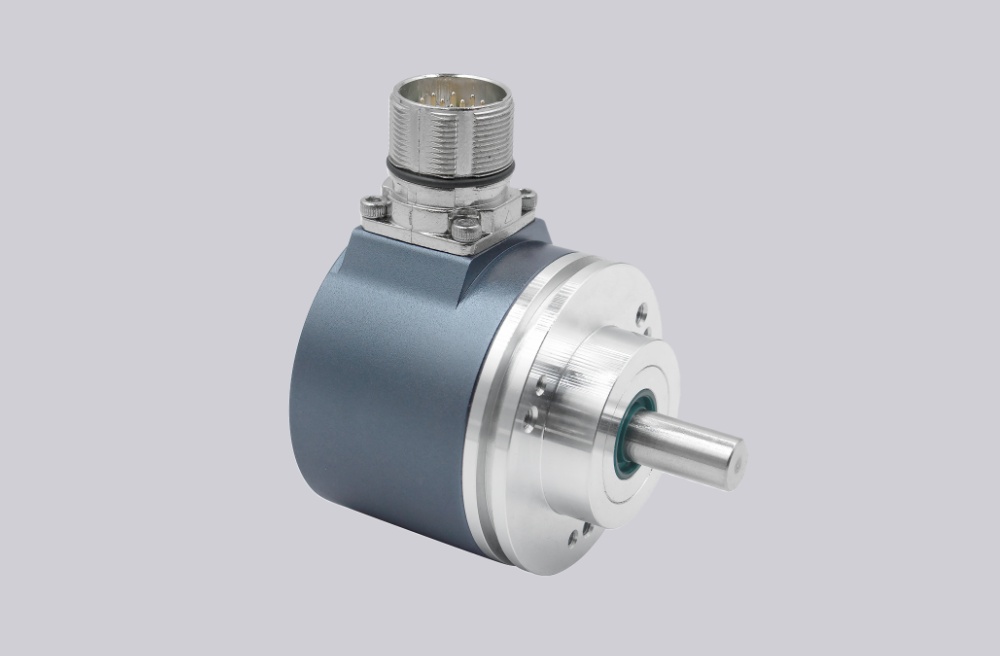
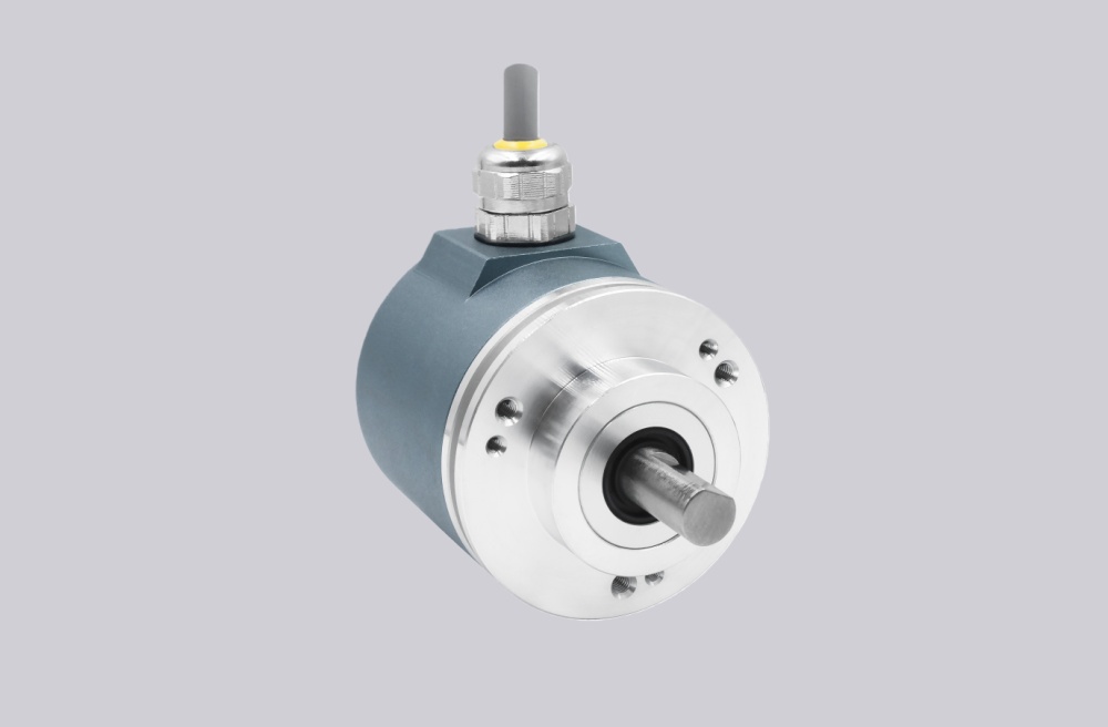
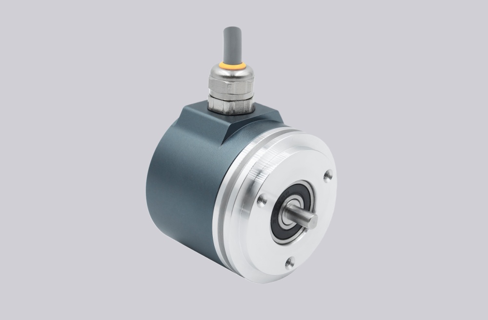
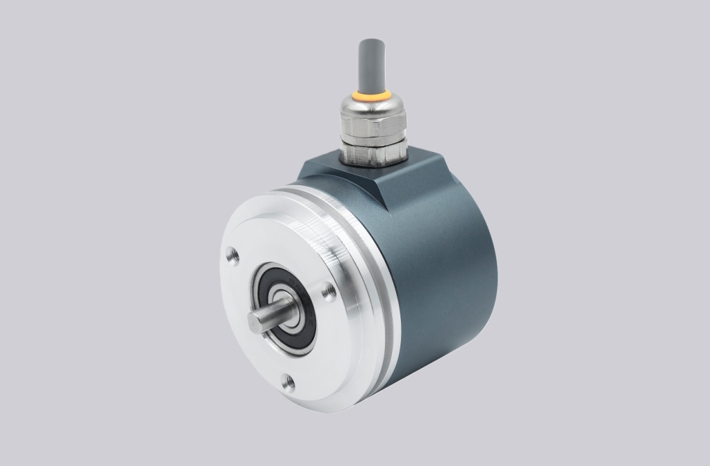
This coded version shares the same electrical platform as the radial-cable model: 13 bit single-turn, 12 bit multi-turn, Gray-code SSI, and 25-bit transmission without parity. The main difference lies in the “4” connection code, which indicates a 1 m axial cable outlet. Combined with the BMA servo flange and 6 mm shaft, this arrangement is often selected where straight cable pull or rear cable routing is preferred inside compact housings or drive-side mounting spaces.
Industrial Integration Considerations
The electrical protocol is similar to the radial-cable version, but the practical retrofit focus is different. For this model, the main integration concern is whether the axial cable direction aligns with the existing enclosure path, gland orientation, and bending clearance. On the controller side, SSI clock handling, Gray-code decoding, and the 25-bit output word should still be checked. ZERO and F/R input logic should also be verified where the original application depends on defined startup direction or field zeroing.
Field Installation and Wiring Notes
The axial cable version is more sensitive to straight cable pull and rear-space clearance than the radial version. During installation, the cable should not be forced into an immediate bend near the encoder exit, and the shielded signal lines should remain separated from power conductors. Since cable-output versions connect the screen to the housing, EMC continuity should be preserved with the original grounding scheme. The ZERO input should be applied only after confirming F/R direction logic, and the 6 mm shaft with servo flange mounting should be checked for clean alignment before energizing the system.
Custom Compatible Encoder Solution
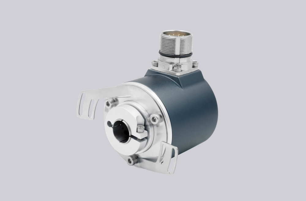
The compatible solution for this version is generally engineered around axial cable routing continuity, 25-bit Gray-code SSI output, 6 mm shaft fit, servo flange mounting geometry, and preserved control-input behavior for ZERO and F/R. If the field layout depends on a specific cable pull direction or cabinet entry position, that should be matched during engineering review.
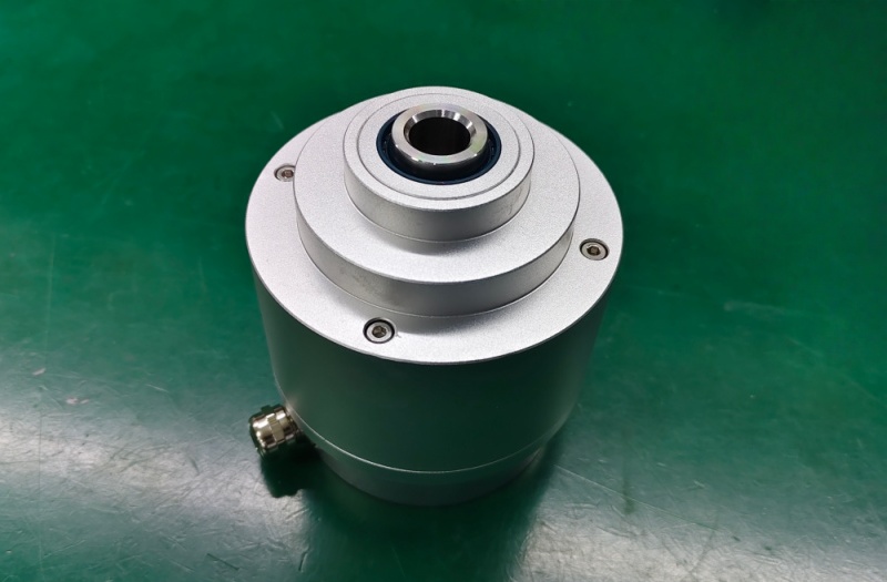
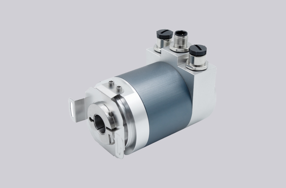
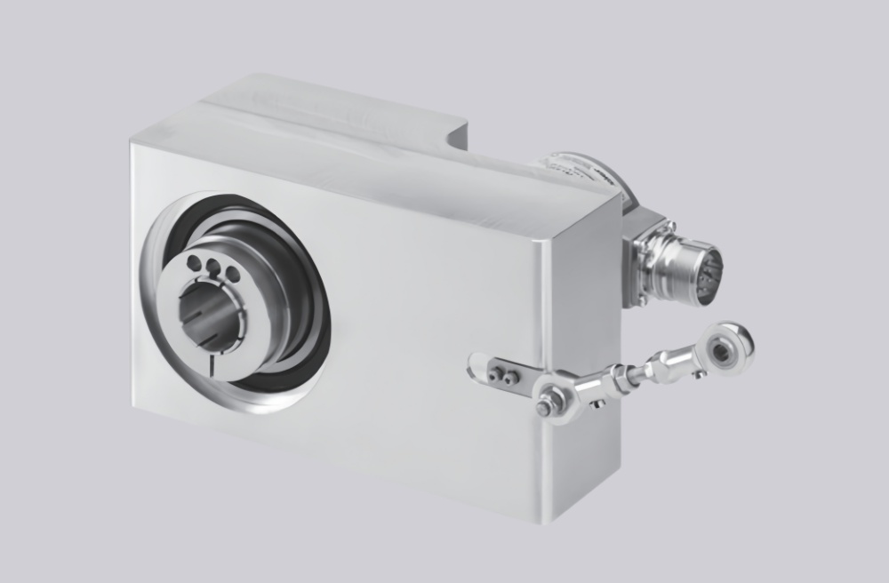
Custom Solution Photos
Lead Time and Custom Development
Typical production lead time: 15 working days. Custom development support is available where the original installation requires preservation of axial cable orientation, shaft fit, and SSI data continuity. Final coded details should be confirmed before production.
Typical Technical Parameters
| Parameter | Specification |
|---|---|
| Interface | SSI, RS485 complementary |
| Singleturn Resolution | 13 bit |
| Multiturn Resolution | 12 bit / 4096 revolutions |
| Output Code | Gray |
| Data Format | 25 bit, without parity |
| Connection | Cable 1 m, axial |
| Shaft | 6 mm |
| Flange Type | Servo flange |
| Voltage Supply | 10...30 VDC |
| Input Logic | Clock input SSI, F/R input, zero set input |
| Protection | IP65 |
| Temperature Range | -25...+85 °C |