A tailored compatible encoder solution can be developed for BMB 3G.24C8192-C0-A for maintenance, replacement, retrofit, and upgrade tasks. Typical production lead time: 15 working days. This version is particularly suitable for projects where the original installation uses a 10 mm shaft, radial M23 connector, and clamping flange structure, and the replacement should preserve both electrical and mechanical continuity.
Technical Overview of the BMB 3G.24C8192-C0-A Encoder
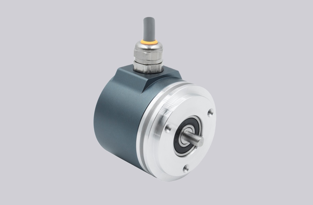
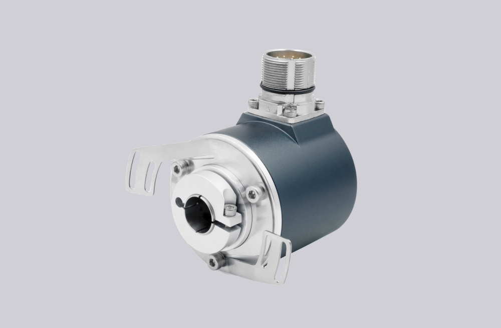
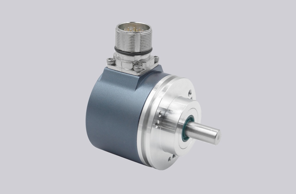
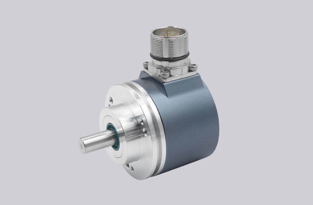
This model uses the same SSI multiturn signal platform as the BMA versions, with 13 bit single-turn resolution, 12 bit multi-turn resolution, Gray-code output, and 25-bit transmission without parity. The major engineering difference is mechanical: BMB denotes the clamping flange version, C0 denotes a 10 mm shaft, and A identifies a radial M23 connector. This makes the model more connector-oriented in field service and more dependent on shaft diameter and flange matching during retrofit.
Industrial Integration Considerations
For this version, connector continuity and shaft fit are the two main integration points. The M23 pin assignment should align with the existing harness, and the controller should support complementary SSI with Gray-code interpretation and 25-bit word handling. Because the unit also includes ZERO and F/R inputs plus DV and DV/MT diagnosis outputs, the receiving system should be reviewed for any existing use of direction control, field zeroing, or basic signal validity monitoring. The 10 mm shaft and clamping flange geometry should also be checked carefully before substitution.
Field Installation and Wiring Notes
The radial M23 connector version requires careful attention to pin continuity, connector clearance, and cable exit direction. The main assignments include +VS, GND, clock+, data+, ZERO, data-, clock-, DV, F/R, and DV/MT. During replacement, the installer should verify the M23 male pin mapping against the existing cable set before energizing the encoder. The clock pair forms a current loop, so controller-side matching should be confirmed. The ZERO input requires a HIGH pulse longer than 100 ms and should be executed after F/R direction selection. Mechanically, the 10 mm shaft and clamping flange should be aligned without forcing the housing, especially in installations with rigid couplings.
Custom Compatible Encoder Solution
A custom compatible solution for this version is commonly built around these points: 10 mm shaft and clamping flange fit, radial M23 connector continuity, 25-bit Gray-code SSI behavior, ZERO and F/R input logic, and preservation of the original field harness layout. Where necessary, the coded version can be reviewed against the original application so commissioning changes remain limited.
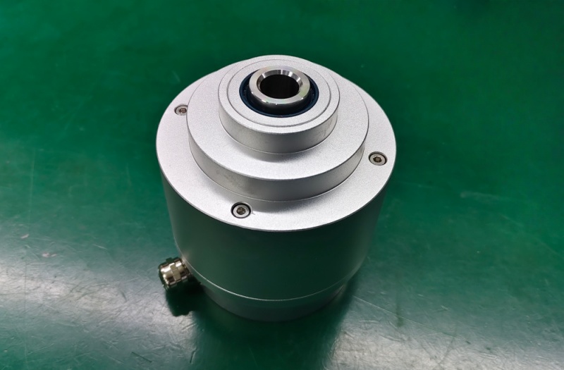
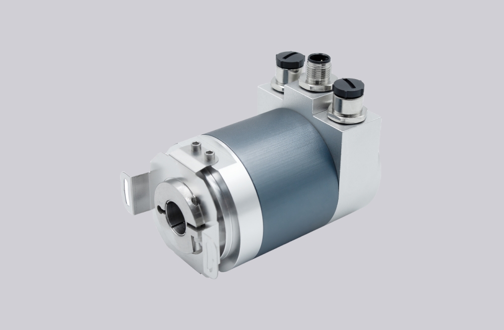
Custom Solution Photos
Lead Time and Custom Development
Typical production lead time: 15 working days. Custom development can be arranged for projects requiring preservation of connector direction, shaft diameter, flange mounting style, and SSI controller matching. Any project-specific use of diagnosis outputs or control inputs should be confirmed during engineering review.
Typical Technical Parameters
| Parameter | Specification |
|---|---|
| Interface | SSI, RS485 complementary |
| Singleturn Resolution | 13 bit |
| Multiturn Resolution | 12 bit / 4096 revolutions |
| Output Code | Gray |
| Data Format | 25 bit, without parity |
| Connection | Connector, radial M23 |
| Shaft | 10 mm |
| Flange Type | Clamping flange |
| Voltage Supply | 10...30 VDC |
| Diagnosis Outputs | DV and DV/MT |
| Protection | IP65 |
| Temperature Range | -25...+85 °C |