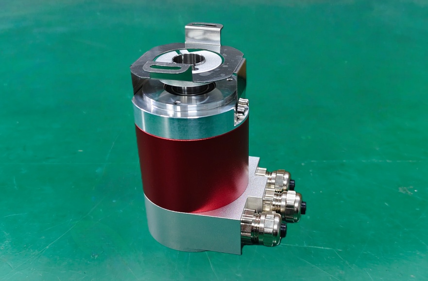
This customized replacement for the DAF65-12B10 is designed as a direct alternative for systems using a 4–20 mA absolute output. Electrical characteristics and mechanical dimensions are carefully matched to enable true drop-in installation, avoiding redesign or commissioning changes. Through a flexible customization process, this solution helps users optimize replacement cost while maintaining functional consistency with the original encoder. Typical production lead time is approximately 15 working days, supporting fast response to maintenance or supply chain gaps.
The replacement encoder delivers stable current-loop performance, ensuring reliable signal transmission in applications with long cable runs or high electromagnetic interference. Absolute position feedback remains precise and repeatable, supporting long-term operational stability. In addition to standard configurations, low-volume and non-standard customization can be accommodated, making this solution suitable for industrial automation, material handling equipment, and process control systems requiring rapid, dependable encoder replacement.
Electrical data
| Parameter | Value |
| Valid for all versions | Unless otherwise stated |
| Sensor system: | GaAIAs diode, photo-transistor array, precision comparator |
| Setting cycles EEPROM: | ≥10^6 |
| Multifunctional inputs (MFP): | Depending on adjusting mode (signal input E6) |
| Memory circuit (latch): | Through MFP |
| Disc coding: | Gray code |
| Signal sense: | CW or CCW (signal input E6) |
| Supply voltage range V_s: | +20 to +26 VDC, 15±0.5VDC(optional) |
| Supply current I_s: | 80 mA typ. / 120 mA max. (when output current = 0) |
| Linearity: | 0.025% typ. / 0.05% max. (+2 LSB), 12 Bit monotory warranted |
| Temperature drift: | 0.0015% / K typ. |
| Current output | |
| Accuracy | |
| at starting point 0 mA: | 0 mA ±5 μA typ. / ±15 μA max. |
| at end point 4 mA: | 4 mA ±5 μA typ. / ±15 μA max. |
| Load resistance: | 0 to 500Ω at V_s = 20 to 26 VDC, 0 to 1000Ω at V_s = 22 to 26 VDC |
| Voltage output | |
| Accuracy | |
| at starting point 0 V: | 0 V ±2.5 mV typ. / ±7.5 mV max. |
| at end point 10 V: | 10 V ±2.5 mV typ. / ±7.5 mV max. |
| Output current: | 5 mA max. When load resistance > 2 kΩ (short circuit proof) |